DIRECTIONAL CONTROL OF AIRCRAFT
The deflection of the rudder will cause the development of a lift or lateral force that will generate a yawing moment, causing the airplane to seek a new sideslip angle heading. The change in the sideslip angle heading is generally directly influenced by the rudder angle deflection. The center of the lateral force on the rudder can be well above the CG of the airplane which will induce a rolling moment that requires crossed controls if a steady sideslip is required.
Design Requirements. The design requirements for the rudder depend on the type of airplane. For light single engine the rudder design will be based on the sideslipping needed for control of the glide path and alignment of the runway during landing. Thus when operating in a cross wind it is necessary to have a sideslip angle so to touch down the rudder is reversed to allow the aircraft to be aligned to the runway.
The most critical requirement for the rudder is the counteracting of the yawing effect of a failed engine on multi – engine aircraft. This is especially true with aircraft having the engines well outboard on the wing so that large moment arms are involved. With some of the early large turboprop aircraft it was necessary to consider not only the loss of thrust due to the failed engine, but also the possibility of negative thrust due to the propeller developing reverse thrust. In the case of the latter condition the rudder design problem became impossible, thus requiring other solutions.
The conditions for the rudder design are determined by the civil air regulations which define a minimum control speed parameter, VMC > where with the most critical engine out it must be possible to maintain straight flight with zero yaw. The minimum control speed is usually tied in with the stall speed with power and the most aft CG location. Thus, the rudder must be designed to provide sufficient lateral force so that the yaw moment exceeds that exerted by the engine out conditions.
Rudder Control Basically, the effectiveness of the rudder depends upon the flap chord ratio c^/c. As described in the Chapter IX, effectiveness may statistically be indicated by the parameter dfi/d6 ^ 0.5. This value means that deflection of the rudder by 6 – 1° , changes the lateral force as much as it would be changed by a differential of the sideslip angle = 2° . Single-propeller airplanes, such as the fighter in figure 40 for example, have a directional trim or rudder problem. Because of slipstream rotation, the vertical tail is blown to one side. For a right hand propeller, therefore, the airplane tends to turn to the left. The rudder angle required to prevent turning and/or sideslipping, is plotted on figure 41 as a function of the indicated airspeed. To reduce rudder deflection and force required, the fin is usually built onto the fuselage at a small lateral angle, such as iv = 2° in the P-51, for example. Around V = 240 mph, where the rudder angle is zero, the average sidewash angle due to full-power slipstream is evidently equal to that of the tail setting. The rudder angle required for trim grows considerably as the airspeed is reduced.
Analysis. We will assume that power and torque Q of the engine be constant. The average speed w representing slipstream rotation is roughly
w —’ Q/SPV
where SpV = approximation for the rate of volume (and mass) flow through the propeller disk. The sidewash angle is then
w/V 1/Ve (31)
We have plotted in part (B) of figure 40, the rudder angles required for trim, versus l/V8. The function obtained is essentially linear. There are certain secondary effects to be considered, however:
a) For maximum rudder pedal forces of plus-minus 50 lb, some elastic deficiency can be assumed in the rudder angle as recorded.
b) At 90 mph, where the pedal force is 50 lb, the phot is evidently tired to do more. The airplane is sideslipping at/5 = 10°.
c) In the analysis above, the Slipstream velocity v (added in downstream direction) is disregarded. The sidewash angle is actually w / (V + v).
Sideslipping as in (b) can theoretically be eliminated by deflecting the rudder further, corresponding to
Ad = ^(dcT/d/S)
where the derivative has the value of 0.8, as tested for the same condition of flight. Considering elasticity as in (b) above and on account of (c) above, the upper line in graph ■(B) must be expected to level off. The value required at V ■- 0, at the start of the take-off run of the airplane, might be the maximum possible rudder angle, which is 32° for the P-51. If the vertical tail were not be within the slipstream, it could be difficult to handle the P-51 or arty other single-propeller airplane while taxiing on the ground, particularly in lateral wind.
Sideslipping To – increase the drag control the rate of descent and align the airplane With the runway slideslipping is used. To prevent the airplane from sideslipping, the ailerons have to be deflected thus providing an angle of bank. In steady-state and straight sideslipping inotion, conditions are as follows:
the rudder balances the yaw moment, also producing some lateral forge,
the ailerons balance the roll moment, keeping the airplane banked,
a component of the airplane’s weight counteracts the lateral force.
Sideslipping is also a convenient method of testing in flight, stability, control effectiveness, and forces necessary to deflect the control elements.
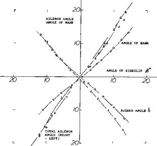
Flight Testing. In an airplane flying in any steady-state equilibrium, there are no “free” moments. Besides speed, all there is to be measured are angles. For one of the many airplanes investigated (31)(33) typical flight-test results are presented in figure 41. The graph shows
the rudder deflection required the aileron angle required the angle of bank required
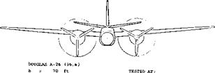
all as a function of the angle of sideslip, gliding at one particular speed of the resulting straight motion, and at the constant lift coefficient CL – 0.6. The aileron deflection neutralizes the roll moment primarily originating in the wing as a consequence of dihedral. From the frontal view of the airplane tested, it is evident that there will not be much of interference between the slipstreams and the central vertical tail. Therefore, results in cruising (power – on) condition are not very much different from those shown in gliding (power-off) condition, for that particular airplane.
|
S = 540 ft2 v = 190 mph d = 12.5 ft q = 92 lb/ft2 |
65 – 215 WING SECTION
2 2000 HP
|
Figure 41. Characteristics of a twin-engine airplane in steady sideslipping motion (33,a). |
Lateral Force. In banked condition, the component of the airplane’s weight in lateral direction is Y = W sin <p, where (f = angle of bank. The lateral force derivative is thus found to be
dCу /d/З = {rf1180)(d у /d/З)(W/qS) (32)
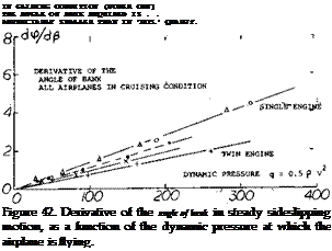
where q = 0.5 ^ V*. Assuming that the force derivative be independent of the angle of attack (lift coefficient), the angle of bank required to balance a certain angle of sideslip, can be expected to vary in proportion to the
dynamic pressure. Flight-test results of several airplanes are plotted in figure 42. For W = 12,000 lb, wing area S = 300 ft2, the loading of the F-47-is W/S = 40 lb/ft* . The lateral derivative is then
dCy /d/З = (W/S)(dy /ifi )/q « 0.010
where dp /Aft = 0.014 as in the graph. This derivative is not the same as in a wind-tunnel model, however. Rather, it represents the lateral force of the airplane in trimmed condition, id est for Cn~ zero.
Yaw Moment. The significance of the flight tests described is found in the fact that the control deflections measured can be used to determine the static stability of the airplane. The yaw moment corresponds to
dCVd/5 = (dd/d/ї )(d/3 /dSXdCjbJdjg )WV (33)
where d/l/dff^= rudder effectiveness ratio,, and dC^/d/3 = lateral force slope of the vertical tail surface used. For example, in figure 41, the derivative dd/d/3 = (do/dy )l(dfi/dp ) = 0.8. A large value of the flight – tested d6 Idfi can indicate two things:
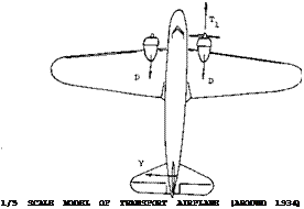
Inopporative Engine. Multi-engine aircraft are desigfiecl so that the airplane can continue to fly after one or more engines fail. When an engine fails a yawing moment is encountered due to the asymmetrical thrust developed by the operating engines and the drag of the dead engine as illustrated on figure 44. This yaw moment may be very large if the propeller on the dead engine is windmilling and the failed engine is capable of absorbing a large amount of torque. For this case the negative thrust produced by the windmilling propeller can be as large as the positive thrust on the operating engines. Thus the yaw moment produced by the vertical tail must be very large’ to balance that moment produced by the failed engine. In many cases the moment required is larger than is-possible with a practical design. As stated in (30,b) the mdst suitable method of flying on one engine, is to balance th& yaV moment by rudder deflection, and to prevent side* slipping by banking the airplane toward the side of the operating engine. The result is a lateral force primarily in the vertical tail surface, supporting a srtialter part df thef airplane’s weight, in a manner similar to that as explained in connection with figure 42. An example for this mode of operation is shown in figure 43. To be able to maneuver, the make turns and to. climb after a landing approach may have failed, it is desirable that full power of the operating engine be used. As stated in (30,d) “the asymmetric power condition, to a large extent dictates the design of the vertical tail surface”.

1. that the rudder effectiveness (d$ /dd) is small,
2. that directional stability (resulting from the last half of the equation) is large. The effectiveness can be
estimated (see doc/dcf in Chapter IX) or it may be assumed to have an average value, say of 0.6 for rudders. For a conventional type rudder, therefore, the (flight – tested derivative dd /d/S is considered to be a measure for the directional stability
dC??/d>5~(drf7d>S) (34)
Using the tail volume ratio V/ = 0.054 and the statistical value ofdC^i/d/6= 0.04, the directional stability derivative of the airplane in figure 41, may thus be
dCyd/3 = 0.8 (0.6) 0.04 (0.054) » 0.001
O F-47 FIGHTER
4 F-39 FIGHTER AS IN (35,d)
• P-51 AS IN FIGURE’40
X DEHAV "MOSQUITO"'(36>b) f DOUGLAS A-26, TWIN (36,a)

 b = 20° RUDDER ANGLE TO COMPENSATE Cn
/3 = 8° RESULTANT ANGLE OF SIDESLIP
2° ANGLE IN BANKED MODE 11° RUDDER ANGLE IN THIS MODE
Figure 43. Example (30,b) for the operation of an airplane with one of two engines inoperative.
Yaw Moment. In the design of the vertical tail surface for the engine out case the low speed take-off condition is critical. Here the dynamic pressure is low so that the deflection and area required to droduce the necessary lateral force is very high.
As an example of a somewhat more powerful configuration, the one-engine operation of the B-28 (as in figure 39) may be analyzed. As indicated in (27,c) maximum – power thrust in one propeller is approximately T = 0.1. W. The corresponding moment is “N” = 0.1 (32,000) 11 = 36,000 (ft-lb) where the moment arm to the CG is 11 ft. To balance (trim) this moment, the vertical tail surface has to provide a lateral force Y = 36,000/28 = 1300 lb, for its moment агт^и = 28 ft. Based on a tail area = 75 ft2, the corresponding lateral force coefficient is
CIa/ = 130°/(75 0.5 ^ Vе)
As found in the “control” chapter, the maximum coefficient producible by 25° rudder deflection, at zero angle of sideslip, is in the order of 0.6. For comparison, the coefficient obtained in (30,e) for 30° rudder deflection, is 0.63. Solving now the last equation, a minimum permissible speed of 106 mph is obtained. The corresponding lift coefficient of the airplane is CL =1.6. This may be close to the maximum lift coefficient of this airplane in power – off (landing) condition. Disregarding rudder pedal forces, therefore, the B-28 appears to have satisfactory qualities in one-engine operation.


