Forces on an Arbitrary Finite Wing from Lifting-Line Theory
We now apply the lifting-line theory to estimate important aerodynamic properties of a finite wing of arbitrary shape and airfoil.
1. Lift Force
From the Kutta-Joukouski Theorem, the lift per unit span is related to the circulation by L’= рУгоГ. Thus, the total lift on the wing is obtained by integrating the lift per unit span across the span; namely:
b/2 b/2
L= J L’dy ^ L’ = Г(y)dy. (6.28)
-b/2 – b/2
The wing-lift coefficient is given by:
Standard notation is that the forces on a three-dimensional wing are unprimed, and the wing-force coefficients are written with an upper-case subscript. The nondimensionalization is with the wings planform area, S.
Transforming to the angular-measure variable, 0, and integrating:
The product [(sin(n0))(sin)], when integrated between the limits n and 0, is zero for n Ф 1. Thus, only the Ai term remains and:
CL = nAiAR. (6.30)
Recall that the aspect ratio, AR, is a wing-planform property and AR = b2/S.
Eq. 6.30 shows that the wing-lift coefficient depends on only one Fourier – series coefficient. This does not mean that the fundamental monoplane equation must be applied at only one spanwise station. The more simultaneous equations that are generated for the An’s, the more accurate is the value for Ai.
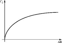
The variation of wing-lift coefficient with AR for a tapered wing is shown in Fig. 6.15. This is not simply a linear plot, as Eq. 6.30 might suggest, because the value of Ai changes with AR. Wing lift and the wing lift-curve slope are discussed later.
Figure 6.15. Variation of the wing-lift coefficient with the AR for a tapered wing.
 2. Induced Drag Force
From Eq. (6.18), the induced drag is given by D = L’a;. Then, L’ may be written as a Fourier-series expression by using Eqs. 6.17 and 6.23. The expression for a; is given by Eq. 6.15 and the integral in Eq. 6.15 already was evaluated as Eq. 6.26. Dropping the subscripts in Eq. 6.26:
A= J [L’][ai](dy):
-b/2

![]()
and
We note that the integrand is the product of two summations. The running subscript in the second summation is changed to m to emphasize this point. Now:
n j 0 n * m
J sin и0sin m0d0 = – j n
0 (2 n=m.
Expanding the two Fourier-series, multiplying term, by term, and then integrating yields:
|
CD =2AR |
‘n’ о |
A2 + Z nAn2 |
= nAR( A-j2) |
1+Zn |
( л2 ‘ A2 |
|
V 2 J |
_ n=2 _ |
n=2 |
V A12 JJ |
Notice that the summation is always a positive quantity, because all of the An’s appear as the square. This summation has a value that depends on the values of the Fourier-series coefficients and, hence, on the wing planform. We give this summation the symbol 5 , which is known for a specified wing planform. Finally, we use Eq. 6.30 to substitute for Ab The result is:
This is an important result. It states that the induced-drag coefficient depends on the lift coefficient squared, so that a portion of the drag of an airplane is the result of the production of lift. Notice the importance of the AR. Recall the discussion in Chapter 1 about the Voyager airplane used for the first nonstop flight around the earth and the illustrations showing high-performance sailplanes. ARs that sometimes exceed 50 are used as one of several drag-reducing design features for such specialized aircraft, which require the lowest possible drag in the lower speed range. (Boermans, 2006 and Dillinger and Boermans, 2006).
Because § > 0, then for a given AR, the induced drag is a minimum when § = 0. The conditions necessary for this to be so are studied shortly. The quantity (1 + §) often is written as 1/e, where e is called the span efficiency factor. This parameter is used frequently in the aeronautical industry as a measure of the efficiency of the wing design in reducing induced drag. For minimum induced drag, e = 1.0. As induced drag increases, the value of e decreases. Then, Eq. 6.31 may be written alternately as:
For a typical wing, § is a small quantity on the order of 0.05 (corresponding to e = 0.952). Thus, the AR has a much larger role in setting the magnitude of the induced drag than the span-efficiency factor. Induced drag is discussed further in a subsequent section.
 |
Now, we run Program PRANDTL to explore the dependence of lift and induced drag on all of the parameters that describe a tapered wing.
Elliptic-Lift Distribution
The results for the calculation of the induced drag of an arbitrary finite wing, Eq. 6.32, indicated that the drag was least when all of the An’s in the Fourier series were zero for n >1. This section examines the performance of a wing when the
induced drag is minimum and then investigates the wing geometry that is necessary to achieve this minimum induced-drag condition.
1. Elliptic Loading
The general Fourier-series expression for Г(0), the spanwise circulation distribution, is given by Eq. (6.23). With all of the An’s set equal to zero except Ab this equation reduces to:
Г = 2bV^A1sin 0 (6.33)
At the root section y = 0 (0 = n/2), let Г = Г0, where:
![]()
![]() Г0 = 2bV^Ai.
Г0 = 2bV^Ai.
Then, Eq. 6.34 may be written as:
Г = Г0 sin 0.
 |
||
Now, we recall from a trigonometric identity that sin2 + cos2 = 1. We also recall from the spanwise location transformation, Eq. 6.22, that y = (b/2) cos 0. It follows that:
Then, substituting this relationship into Eq. 6.35 and rearranging:
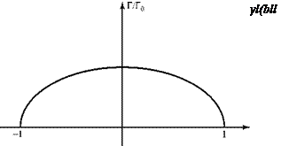
which is the equation for an ellipse in y-Г coordinates, as illustrated in Fig. 6.16. This result states that if the bound vorticity, or circulation Г, and therefore the lift per unit span, L’, is distributed eliptically across the wing span (i. e., elliptical loading) then the induced drag is a minimum.
 |
|
The elliptical-loading results that follow are useful because they represent a standard for comparison. They also are used as a basis to express results for arbitrary spanwise loading by means of a correction factor (compare Eqs. 6.32 and 6.44).
In the remainder of this section, notice the repeated appearance of the ratio b2IS, which is the reason that the special name aspect ratio was given to this quantity. Also notice the primary role of the AR in both the elliptical-spanwise-loading results and those for arbitrary spanwise loading.
2. Wing Lift
Recall that L’ = рУ^Г and use the spanwise-location transformation, Eq. 6.22. Then, for elliptical loading, Eq. 6.35, the wing lift is given by:
 b/2 0
b/2 0
L= J L’dy = Jpyjr„sin0]
 |
|
-b/2
3 Downwash
The general expression for the downwash is given by Eq. 6.10, where dr/dy may be written as (dr/d0) (d0/dy). For elliptical loading, dr/d0 = r0cos 0 from Eq. 6.35. Thus, Eq. 6.10 becomes:
Inverting the limits and placing a minus sign in front of the integral to compensate, the integral has a principle value of n, given by Eq. 6.25 with n = 1. The downwash at any point along the span then is given by:
Г
w = –°. (6.40)
This equation indicates that in the special case of elliptical loading, the down – wash is a constant all along the span. Thus, for a wing with elliptic loading, stall occurs all along the span at the same time. Now, using Eq. 6.39:
The magnitude of the downwash thus depends on the magnitude of the wing-lift coefficient and varies inversely as the wing AR.
4. Induced Angle of Attack
The expression for the induced angle of attack follows from Eq. 6.43 and the definition of a;, Eq. 6.14. Thus,
and the Induced angle of attack also 1s constant across the span.
5. Induced Drag
From Eq. 6.18, D = L’a so that:
and us1ng Eq. (6.42):
![]() C
C
CD= CD =
1 Dimin nAR
The Induced drag Increases as the lift coefficient 1s squared.
6. Relations ships Between Section and Wing Coefficients
From Eqs. 6.12 and 6.13, the section-lift coefficient for a finite wing may be written as:
Ct = mo(a — a i — «L0). (6.45)
Now, we assume an untwisted wing of constant section with elliptical loading. Under this condition: a = constant across the span, untwisted (no geometric twist) wing aL0 = constant across the span, wing of constant section a; = constant across the span, elliptical loading
The two-dimensional lift-curve slope, m0, has the theoretical value 2n, and experimental values are not greatly different from that value. Then, if m0 is assumed constant, for an untwisted wing of constant section with elliptical spanwise-lift distribution, Eq. 6.45 states that the section-lift coefficient, Cl, must be constant across the span and further more that:
– ь/2 – ь/2 c ь/2
CL =J L’dy = 1 [<7Cic]dy = ~^ J cdy = C – (6.46)
q°°S —Ь/2 q°°S —Ь/2 S —Ь/2
because the integral of the chord over the span is simply the planform area. Thus, under these assumptions, the numerical value of the section and wing-lift coefficients is the same. Similarly,
so that under these same assumptions, the numerical value of the section and wing induced-drag coefficients are the same.


