Mach waves
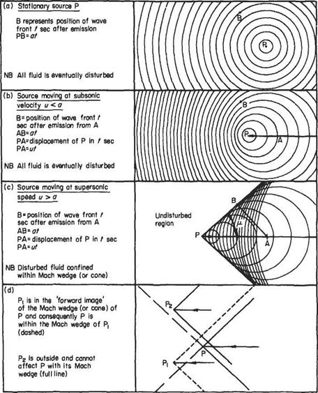
Figure 6.11 shows the wave pattern associated with a point source P of weak pressure disturbances: (a) when stationary; and (b) and (c) when moving in a straight line.
(a) In the stationary case (with the surrounding fluid at rest) the concentric circles mark the position of successive wave fronts, at a particular instant of time. In three-dimensional flow they will be concentric spheres, but a close analogy to the
|
Fig. 6.11 |
two-dimensional case is the appearance of the ripples on the still surface of a pond from a small disturbance. The wave fronts emanating from P advance at the acoustic speed a and consequently the radius of a wave t seconds after its emission is at. If t is large enough the wave can traverse the whole of the fluid, which is thus made aware of the disturbance.
(b) When the intermittent source moves at a speed и less than a in a straight line, the wave fronts adopt the different pattern shown in Fig. 6.11b. The individual waves remain circular with their centres on the line of motion of the source and are eccentric but non-intersecting. The point source moves through a distance ut in the time the wave moves through the greater distance at. Once again the waves signalling the pressure disturbance will move through the whole region of fluid, ahead of and behind the moving source.
(c) If the steady speed of the source is increased beyond that of the acoustic speed the individual sound waves (at any one instant) are seen in Fig. 6.11c to be eccentric intersecting circles with their centres on the line of motion. Further the circles are tangential to two symmetrically inclined lines (a cone in three dimensions) with their apex at the point source P.
While a wave has moved a distance at, the point P has moved ut and thus the semivertex angle
.at. 1
a = arc sin— = arc sin— (6.58)
ut M v ‘
M, the Mach number of the speed of the point P relative to the undisturbed stream, is the ratio и/a, and the angle ц is known as the Mach angle. Were the disturbance continuous, the inclined lines (or cone) would be the envelope of all the waves produced and are then known as Mach waves (or cones).
It is evident that the effect of the disturbance does not proceed beyond the Mach lines (or cone) into the surrounding fluid, which is thus unaware of the disturbance. The region of fluid outside the Mach lines (or cone) has been referred to as the zone of silence or more dramatically as the zone of forbidden signals.
It is possible to project an image wedge (or cone) forward from the apex P, Fig. 6.1 Id, and this contains the region of the flow where any disturbance Pb say, ahead would have an effect on P, since a disturbance P2 outside it would exclude P from its Mach wedge (or cone); providing always that Pi and P2 are moving at the same Mach number.
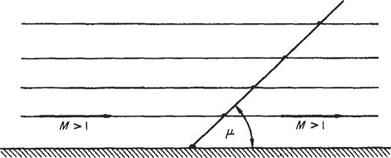
If a uniform supersonic stream M is superimposed from left to right on the flow in Fig. 6.11c the system becomes that of a uniform stream of Mach number M > 1 flowing past a weak disturbance. Since the flow is symmetrical, the axis of symmetry may represent the surface of a flat plate along which an inviscid supersonic stream flows. Any small disturbance caused by a slight irregularity, say, will be communicated to the flow at large along a Mach wave. Figure 6.12 shows the Mach wave emanating from a disturbance which has a net effect on the flow similar to a pressure pulse that leaves the downstream flow unaltered. If the pressure change across the Mach wave is to be permanent, the downstream flow direction must change. The converse is also true.
|
|
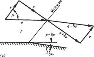
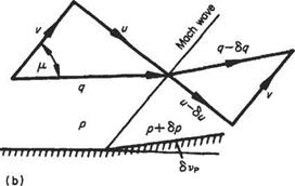
It is shown above that a slight pressure change in supersonic flow is propagated along an oblique wave inclined at p to the flow direction. The pressure difference is across, or normal to, the wave and the gas velocity will alter, as a consequence, in its component perpendicular to the wave front. If the downstream pressure is less, the flow velocity component normal to the wave increases across the wave so that the resultant downstream flow is inclined at a greater angle to the wave front, Fig. 6.13a. Thus the flow has been expanded, accelerated and deflected away from the wave front. On the other hand, if the downstream pressure is greater, Fig. 6.13b, the flow component across the wave is reduced, as is the net outflow velocity, which is now inclined at an angle less than p to the wave front. The flow has been compressed, retarded and deflected towards the wave.
Quantitatively the turning power of a wave may be obtained as follows: Figure 6.14 shows the slight expansion round a small deflection <5vp from flow conditions p, p, M, q, etc., across a Mach wave set at p to the initial flow direction. Referring to the velocity components normal and parallel to the wave, it may be recalled that the final velocity q + 6q changes only by virtue of a change in the normal velocity component и to и + би as it crosses the wave, since the tangential velocity remains uniform throughout the field. Then, from the velocity diagram after the wave:
(q + 8q)2 = (u + Su)2 + v2
|
|
|
|
q + 2q6q + (6q)2 = u2 + 2 иёи + (6u)2 + v2 and in the limit, ignoring terms of the second order, and putting i? + v2 = q2:
qdq = udu (6.59)
Equally, from the definition of the velocity components:
и. . 1 dM v.
и = arc tan – and du =—————- , — = ~^au
v 1 + (u/v)2 v q2
but the change in deflection angle is the incremental change in Mach angle. Thus
![]()
![]() v
v
Combining Eqns (6.59) and (6.60) yields
![]()
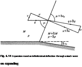 |
dq и. и
-— = q – since – = arc tan u =
dvp v v JM2 1
T’ = ±’7^=T = ±dvptan/x ^6’61^
Ч у M2 — 1
where q is the flow velocity inclined at vp to some datum direction. It follows from Eqn (6.10), with q substituted for ji, that
 |
 |
Fig. 6.15
or in pressure-coefficient form
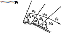
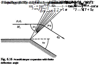
The behaviour of the flow in the vicinity of a single weak wave due to a small pressure change can be used to study the effect of a larger pressure change that may be treated as the stun of a number of small pressure changes. Consider the expansive case first. Figure 6.15 shows the expansion due to a pressure decrease equivalent to three incremental pressure reductions to a supersonic flow initially having a pressure p and Mach number M. On expansion through the wavelets the Mach number of the flow successively increases due to the acceleration induced by the successive pressure reductions and the Mach angle (p = arc sin l/M) successively decreases. Consequently, in such an expansive regime the Mach waves spread out or diverge, and the flow accelerates smoothly to the downstream conditions. It is evident that the number of steps shown in the figure may be increased or the generating wall may be continuous without the flow mechanism being altered except by the increased number of wavelets. In fact the finite pressure drop can take place abruptly, for example, at a sharp comer and the flow will continue to expand smoothly through a fan of expansion wavelets emanating from the comer. This case of two-dimensional expansive supersonic flow, i. e. round a corner, is known as the Prandtl-Meyer expansion and has the same physical mechanism as the one-dimensional isentropic supersonic accelerating flow of Section 6.2. In the Prandtl-Meyer expansion the streamlines are turned through the wavelets as the pressure falls and the flow accelerates. The flow velocity, angular deflection (from some upstream datum), pressure etc. at any point in the expansion may be obtained, with reference to Fig. 6.16.
Algebraic expressions for the wavelets in terms of the flow velocity be obtained by further manipulation of Eqn (6.61) which, for convenience, is recalled in the form:
Introduce the velocity component v = q cos fj, along or tangential to the wave front (Fig. 6.13). Then
![]() (6.64)
(6.64)
It is necessary to define the lower limiting or datum condition. This is most conveniently the sonic state where the Mach number is unity, a = a*, vp = 0, and the
 |
|
wave angle fj, = 7t/2. In the general case, the datum (sonic) flow may be inclined by some angle a to the coordinate in use. Substitute dvp for (ljq)dqj tan/л from Eqn (6.61) and, since <7 sin/і = a, Eqn (6.64) becomes dvp — d/x = dv/a. But from the energy equation, with c = ultimate velocity, a2/(7 — 1) + (q2/2) = (c2/2) and with q2 = (v2 + a2) (Eqn (6.17)):
which allows the flow deflection in Eqn (6.67) to be expressed as a function of Mach angle, i. e.
 (6.68)
or (6.68a)
In his original paper Meyer[30] used the complementary angle to the Mach wave (ф) = [(тг/2) – д] and expressed the function
as the angle ф to give Eqn (6.68a) in the form
![]() vp — a = ф — ф
vp — a = ф — ф
The local velocity may also be expressed in terms of the Mach angle /і by rearranging the energy equation as follows:
 |
q2 a2 c2 V + r = —
but a2 = q2 sin2 /і. Therefore or
 (6.69)
Equations (6.68) and (6.69) give expressions for the flow velocity and direction at any point in a turning supersonic flow in terms of the local Mach angle fi and hence the local Mach number M.
Values of the deflection angle from sonic conditions (vp – a), the deflection of the Mach angle from its position under sonic conditions ф, and velocity ratio q/c for a given Mach number may be computed once and for all and used in tabular form thereafter. Numerous tables of these values exist but most of them have the Mach number as dependent variable. It will be recalled that the turning power of a wave is a significant property and a more convenient tabulation has the angular deflection (vp — a) as the dependent variable, but it is usual of course to give a the value of zero for tabular purposes.1′
 |
Fig. 6.17
Compression flow through three wavelets springing from the points of flow deflection are shown in Fig. 6.17. In this case the flow velocity is reducing, M is reducing, the Mach angle increases, and the compression wavelets converge towards a region away from the wall. If the curvature is continuous the large number of wavelets reinforce each other in the region of the convergence, to become a finite disturbance to form the foot of a shock wave which is propagated outwards and through which the flow properties change abruptly. If the finite compressive deflection takes place abruptly at a point, the foot of the shock wave springs from the point and the initiating system of wavelets does not exist. In both cases the presence of boundary layers adjacent to real walls modifies the flow locally, having a greater effect in the compressive case.


