Our heavyweight helicopter equal in the world does not have
In Rostov started production of the most load-lifting rotary-wing car The Russian holding «Helicopt[...]

Everything about aircrafts and helicopters. News and events in aviation worldwide. Civil, transportation, military helicopters and airplanes.

Everything about aircrafts and helicopters. News and events in aviation worldwide. Civil, transportation, military helicopters and airplanes.

Everything about aircrafts and helicopters. News and events in aviation worldwide. Civil, transportation, military helicopters and airplanes.

Everything about aircrafts and helicopters. News and events in aviation worldwide. Civil, transportation, military helicopters and airplanes.


It is reasonable to expea that the boundary layer on the blade—being composed of molecules directly affected by the surface—would have a centrifugal force that would tend to produce a flow outboard toward the tip and that this radial flow would represent a power loss. Measurements of flow in the boundary layer of a hovering rotor reported in reference 1.17, however, indicate that the flow is slightly inboard instead of outboard. The direction of flow appears to be a function of four effects: centrifugal pumping, wake contraction, spanwise pressure gradient, and undeveloped tip vortex. In different flight conditions, one or more of these predominate to produce either inboard or outboard flow. The conclusion based on what is now known of the problem is that neglecting radial flow is an acceptable assumption.
Ground Effect
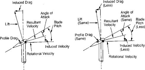
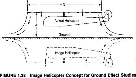
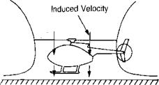
Just as with an airplane, the helicopter flying close to the ground requires less power than when it is flying far from the ground. The source of this ground effect for a hovering helicopter may be visualized by picturing an image rotor flying upside down at the same distance below the ground as the actual rotor is above it, as shown in Figure 1.38. The image wake is considered to be formed of a series of spiral vortex filaments generated at the blade tips and carried up by the image rotor induced velocity. The upward velocity induced in the plane of the actual rotor by the image set of vortex filaments can be calculated and used as a correction to the normal induced velocity term in the power equation. From a blade element standpoint, the reduction in power corresponds to the reduction of rearward tilt of the lift vector, as shown in Figure 1.39. From that figure, it may be seen that in order to maintain the same angle of attack, and thus thrust, the blade pitch must be reduced when flying in ground effect. (That the presence of the ground can influence the flow conditions at the rotor can be demonstrated at the breakfast table. The characteristics of the stream of syrup at the lip of the pitcher can be changed depending on how high it is above the pancake.)
Out of Ground Effect In Ground Effect
|
![]()

z/D
O. G.E.
1
.75
.5
.25
125
Symbol
о
□
A
v
0
0
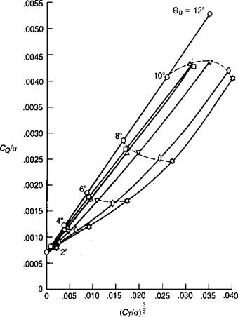
Source: Knight & Hefner, “Analysis of Ground Effect on the Lifting Airscrew,” NACA TN 835, 1941.
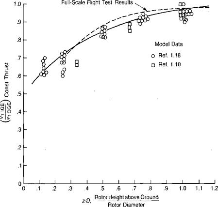
The key to the ground-effect analysis is how much the induced velocity at the rotor disc is reduced compared to what it would be out of ground effect. Figure 1.40 shows the measured effect of the ground on one of several model rotors reported. in reference 1.18. These and similar model test results from reference 1.10 have been used to determine the induced velocity ratio as a function of rotor height using the difference in the torque/solidity coefficient at a constant thrust/solidity coefficient. The results of this analysis are shown in Figure 1.41. An extensive study of the hover performance of helicopters tested by the Army is reported in reference 1.19. The results are shown as a dashed line in Figure 1.41.
The classical studies of ground effect on hovering rotors are found in references 1.18 and 1.20. In these studies, primary emphasis was placed on the ratio of thrust in ground effect to thrust out of ground effect at constant power. For many calculations, such as for hover ceiling in ground effect, however, it is more convenient to be able to compute the power required at constant rotor thrust. The
|
Sources: Circles: Knight & Hefner, "Analysis of Ground Effect on the Lifting Airscrew," NACA TN 835,1941; squares: Bellinger, “Experimental Investigation of Effects of Blade Section Camber and Plan – form Taper on Rotor Performance,” USAAMRDLTR 72-4,1972; dashed line: Hayden, "The Effect of the Ground on Helicopter Hovering Power Required," AHS 32nd Forum, 1976.
out-of-ground-effect main rotor power is the sum of the profile and induced power;
If the rotor thrust is held constant while approaching the ground, the angle of attack of each blade element and the corresponding profile power can be considered to be a constant. The main rotor power in ground effect is thus:
 |
|||
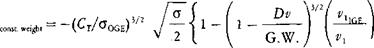
or in nondimensional form:
This applies to an isolated rotor. An actual helicopter will generally exhibit somewhat more benefit from ground effect than that measured on an isolated rotor because of the accompanying decrease in fuselage download. Surveys made below a rotor hovering at Z/D — 0.5 and reported in reference 1.21 showed an upwash inboard of the 40% radius station. Also shown in the same reference is the download on a disc with a radius of 40% of the rotor radius and located 0.16 R below the rotor. For values of Z/D < 0.75, the disc actually produced an upload rather than a download. Further experimental evidence of the effect of the ground on download is presented in reference 1.22, where it is shown that the installation of a wing on a Boelkow BO 105 caused a significant increase in the power required to hover out-of-ground effect but no increase to hover in-ground effect. This loss of vertical drag in ground effect results in a slight modification of the equation for the change in torque:

 ACJo
ACJo
For the example helicopter:
Ст/^oge ~~ 0-085
and
![]() Dv
Dv
G. W.
If it is hovering at 30% of its rotor diameter, from Figure 1.41:
0. ![]() 75
75
|
Дс8/°~-і«ь. = 0-0()0143
which corresponds to a decrease of 407 h. p. out of a total of approximately 2,000 h. p.
For studies in which the thrust ratio at constant power is required, the following equation can be used:
If the difference in profile power is considered to be negligible, this equation reduces to:
IGE
![]() lOGE / const, thrust
lOGE / const, thrust
The wake in ground effect is not really a steady flow, as is assumed by the theory, but a flow with large-scale fluctuations that can be felt as gusts by an observer standing near the helicopter. Reference 1.21 speculates that these fluctuations are associated with the vortex that is made up of the individual vortices from the blade roots. This vortex apparently writhes like a pinned snake along the ground, causing the entire wake to shift and wobble.
Pilots occasionally report that when hovering in ground effect, they experience random yaw disturbances. This is probably due to the effect of the root vortex as it writhes near the tail rotor. Although we cannot see the local unsteadiness in the rotor’s wake, a good analogy is the local unsteadiness in a swiftly moving river. An experimental observation of this phenomenon is reported in reference 1.23, in which an instrumented helicopter model hovering with a main rotor height of one-fourth diameter experienced random vertical stabilizer force variations of 20-30% of the mean value. The variations disappeared when the rotor height was raised to half a diameter.
Many pilots claim that the ground effect over tall grass or water is less than over a solid surface. At this time there are no test data either supporting or refuting the claim.