The shock polar
Although in practice plane-shock-wave data are used in the form of tables and curves based upon the shock relationships of the previous section, the study of shock waves is considerably helped by the use of a hodograph or velocity polar diagram set up for a given free-stream Mach number. This curve is the exit velocity vector displacement curve for all possible exit flows downstream of an attached plane shock in a given undisturbed supersonic stream, and to plot it out requires rearrangement of the equations of motion in terms of the exit velocity components and the inlet flow conditions.
 |
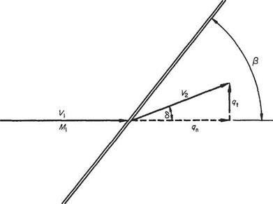
Reference to Fig. 6.25 shows the exit component velocities to be used. These are qt and qn, the radial and tangential polar components with respect to the free stream V direction taken as a datum. It is immediately apparent that the exit flow direction is given by arctan(<7t/<7n). For the wave angle /3 (recall the additional notation of
Fig. 6.25
Fig. 6.23), linear conservation of momentum along the wave front, Eqn (6.72), gives vi = V2, or, in terms of geometry:
![]() V cos /3 = V2 cos(/3 — 6) Expanding the right-hand side and dividing through:
V cos /3 = V2 cos(/3 — 6) Expanding the right-hand side and dividing through:
V = V2 [cos S + tan /3 sin 6 or, in terms of the polar components:
y> =
which rearranged gives the wave angle
To express the conservation of momentum normal to the wave in terms of the polar velocity components, consider first the flow of unit area normal to the wave, i. e.
![]()
![]() Pi +PlM? – P2 + Pl^i
Pi +PlM? – P2 + Pl^i
Then successively, using continuity and the geometric relations:
P2 =P + Pi V sin/3[Fi sin/3 – qn sin/3 + qn cos 0 tan <5] P2=Pi+ Pi V sin/3[(V — qn) sin/3 + cos/3]
and, using Eqn (6.89):
P2 =Pi +PV{V – qa)
Again from continuity (expressed in polar components):
pi Vi sin /3 = p2 V2 sin(/3 – S) = p2?n(sin /3 — cos /3 tan <5)
 |
|
or
![]()
 Again recalling Eqn (6.91) to eliminate the wave angle and rearranging: P2 Vi – qn pi
P2 Viqn – ql-qi P1V1
Finally from the energy equation expressed in polar velocity components: up to the wave
![]() (6.96)
(6.96)
and downstream from the wave
![]() (6.97)
(6.97)
Substituting for these ratios in Eqn (6.93) and isolating the exit tangential velocity component gives the following equation:
![]() (6.98)
(6.98)
that is a basic form of the shock-wave-polar equation.
To make Eqn (6.98) more amenable to graphical analysis it may be made nondimensional. Any initial flow parameters, such as the critical speed of sound a*, the ultimate velocity c, etc., may be used but here we follow the originator A. Busemann* and divide through by the undisturbed acoustic speed a:
 (6.99)
where q% = (qt/ai)2, etc. This may be further reduced to
where
 (6.101)
Inspection of Eqn (6.99) shows that the curve of the relationship between qi and qn is uniquely determined by the free-stream conditions (Mi) and conversely one shock-polar curve is obtained for each free stream Mach number. Further, since
A. Busemann, Stodola Festschrift, Ziirich, 1929.
the non-dimensional tangential component qt appears in the expression as a squared term, the curve is symmetrical about the qD axis.
Singular points will be given by setting qt = 0 and oo. For qt = 0,
(M, – qn)2(£ -Mi) = 0
giving intercepts of the qn axis at A:
qn = M (twice) (6.102)
at В
For qt oo, at C,
 qn = -4тМ і +Mi = Mi+ —2 — 7+1 (7+l)Afi
For a shock wave to exist Mi > 1. Therefore the three points B, A and C of the qD axis referred to above indicate values of qn < Mi, = Mi, and > Mi respectively. Further, as the exit flow velocity cannot be greater than the inlet flow velocity for a shock wave the region of the curve between A and C has no physical significance and attention need be confined only to the curve between A and B.
 |
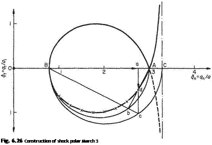
Plotting Eqn (6.98) point by point confirms the values A, В and C above. Fig. 6.26 shows the shock polar for the undisturbed flow condition of Mi — 3. The upper
branch of the curve in Fig. 6.26 is plotted point by point for the case of flow at a free stream of Mi = 3. The lower half, which is the image of the upper reflected in the qa axis shows the physically significant portion, i. e. the closed loop, obtained by a simple geometrical construction. This is as follows:
(i) Find and plot points A, В and C from the equations above. They are all explicitly functions of Mi.
(ii) Draw semi-circles (for a half diagram) with AB and CB as diameters.
(iii) At a given value qn (Oa) erect ordinates to meet the larger semi-circle in c.
(iv) Join c to В intersecting the smaller semi-circle at b.
(v) The required point d is the intercept of bA and ac.
Geometrical proof Triangles Aad and acB are similar. Therefore
ad _ aA aB ac
i. e.
![]() (6.105)
(6.105)
Again, from geometrical properties of circles,
(ac)2 = aB x aC
which substituted in Eqn (6.105) gives
![]() (ad)2 = (aA)2
(ad)2 = (aA)2
Introduction of the scaled values, ad = qu
aB = Oa – OB = qa – Mi, aA — OA – Oa = Mi – qn, aC = OC – Oa = [2/(7 + l)]Mi +Mj – qn
 |
reveals Eqn (6.100), i. e.
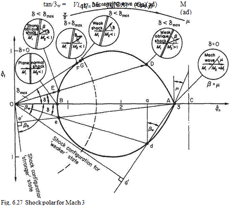
Consider the physically possible flows represented by various points on the closed portion of the shock polar diagram shown in Fig. 6.27. Point A is the upper limiting value for the exit flow velocity and is the case where the free stream is subjected only to an infinitesimal disturbance that produces a Mach wave inclined at p to the free stream but no deflection of the stream and no change in exit velocity. The Mach wave angle is given by the inclination of the tangent of the curve at A to the vertical and this is the limiting case of the construction required to find the wave angle in general.
Point D is the second point at which a general vector emanating from the origin cuts the curve (the first being point E). The representation means that in going through a certain oblique shock the inlet stream of direction and magnitude given by OA is deflected through an angle 6 and has magnitude and direction given by vector OD (or Od in the lower half diagram). The ordinates of OD give the normal and tangential exit velocity components.
 |
The appropriate wave angle Д* is determined by the geometrical construction shown in the lower half of the curve, i. e. by the angle Ada. To establish this recall Eqn (6.99):
![]()
The wave angle may be seen in better juxtaposition to the deflection 6, by a small extension to the geometrical construction. Produce Ad to meet the perpendicular from О in d’. Since AaAdlHA^d’O,
Aod’ = Ada = /?w
Of the two intercepts of the curve the point D yields the weaker shock wave, i. e. the shock wave whose inclination, characteristics, etc., are closer to the Mach wave at A. The other physically possible shock to produce the deflection 6 is represented by the point E.
Point E; by a similar construction the wave angle appropriate to this shock condition is found (see Fig. 6.27), i. e. by producing Ae to meet the perpendicular
from О in e’. Inspection shows that the wave is nearly normal to the flow, the velocity drop to OE from OA is much greater than the previous velocity drop OD for the same flow deflection and the shock is said to be the stronger shock.
As drawn, OE is within the sonic line, which is an arc of centre О and radius [?Jat2 = 1, i-e. of radius
Point F is where the tangent to the curve through the origin meets the curve, and the angle so found by the tangent line and the qn axis is the maximum flow deflection possible in the given supersonic stream that will still retain an attached shock wave. For deflections less than this maximum the curve is intersected in two physically real points as shown above in D and E. Of these two the exit flows OE corresponding to the strong shock wave case are always subsonic. The exit flows OD due to the weaker shocks are generally supersonic but a few deflection angles close to <5max allow of weak shocks with subsonic exit flows. These are represented by point G. In practice weaker waves are experienced in uniform flows with plane shocks. When curved detached shocks exist, their properties may be evaluated locally by reference to plane-shock theory, and for the near-normal elements the strong shock representation OE may be used. Point В is the lower (velocity) limit to the polar curve and represents the normal (strongest) shock configuration in which the incident flow of velocity OA is compressed to the exit flow of velocity OB.
There is no flow deflection through a normal shock wave, which has the maximum reduction to subsonic velocity obtainable for the given undisturbed conditions.


