Trace or Phase Mach Number
The acoustic field generated by a helicopter often tends to be highly focused in one specific direction or series of discrete directions. This is because acoustic waves can accumulate along a front. The focusing of acoustic waves depends on the trace Mach number of the acoustic source point – see Lowson (1968, 1996), Sim (1995, 1996), and Leishman (1999). It is known that the sound waves that have their origin from clusters of source points with supersonic trace Mach numbers on the rotor arrive simultaneously (or nearly so) at the same observer location, thereby generating an acoustic convergence. This is similar to the problem of wave focusing on a ground plane from supersonic flying aircraft that generate sonic booms — see Onyenonwu (1975a, b).
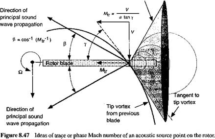
Consider now in more detail the problem of the noise generated by а В VI source point. It will be assumed that the source is acoustically compact. It has been shown previously in Section 8.16.4 that aerodynamic intensity of а В VI depends on the strength of the tip vortex, the distance from the blade to the tip vortex, and the orientation of the vortex to the blade. (See Section 10.4.2 for the method of calculating the ВVI locations over the rotor disk.) The trace Mach numbers of the BVI intersection points between the blade and the axis of the vortex filament inside the rotor disk can, under many conditions, be supersonic. The consequences of this is that the fronts of the spherical sound wavelets generated at the BVI source points on the blades will accumulate along an envelope, similar to a Mach cone generated by a supersonic aircraft. This concept is shown schematically in Fig. 8.47. It is apparent that the principal direction of the sound wave propagation will be normal to the Mach cone.
On a rotor the trace Mach number, Mti, is related to the relative speed of convection of the blade tip vortex axis relative to a blade, V, and the angle of intersection, y, using
Mtr=——, (8.249)
a tan у
|
Wave front envelope (Mach cone)
|
where a is the sonic velocity. A diagram explaining the basic concept is given in Fig. 8.47 for an axis system moving with the rotor. The velocity, V, in Eq. 8.249 must be modified to account for the additional local in-plane convection speed of the vortex filament, which arises from the self-induced effects of the vortical rotor wake or from any blade motion or aircraft maneuver kinematics. It will be apparent from Eq. 8.249 that the trace Mach number can range from subsonic to supersonic, and the trace velocity vector can be directed outward or inward along the blade axis. If the angle of intersection is small, that is, the blade and vortex axes are almost parallel to each other, then the trace Mach number along the blade axis can be significantly supersonic. Figure 8.47 shows that the accumulated wavelet fronts then will propagate into the acoustic field along a ray cone with a semi-vertical angle (5 to the instantaneous trace velocity vector, where f = cos-1 (M^1). Because the value of /3 will vary from point to point on the blade, this effectively forms a series of intersecting ray cones with different vertices and spread angles. The initial conditions of the wavelets are defined by the emission times of all the individual sound fronts that are generated at BVI points with supersonic trace Mach numbers. By numerically computing the positions of the wavelets with respect to time, the pattern of fronts that intersect the plane at any blade angle xfb can be determined.
It is usually desirable to examine the rotor acoustics on a horizontal (ground) plane below the rotor in a frame of reference where the observer moves with the rotor. When the ray cones generated from each supersonic BVI source point in the rotor plane intersect the horizontal ground plane they become conics. This planar intercept is termed an acoustic line because it forms the locus of any acoustic disturbances from the wave fronts that reach the x-y observer plane from the BVI emission points. Notice that after the wavelet intersects the observer plane, the principal direction of the front is along these acoustic lines. If the wave fronts approximately intersect in regions of high acoustic line density, then sound focusing can be said to occur. In forward flight, the radiation cones become distorted by the local flow velocities, although the means of calculating the acoustic lines is the same. By formulating the orientations and intersections of these acoustic lines, which becomes mostly a problem in analytic geometry, it gives a measure of the qualitative directivity of the dominant sound in the far-field as produced by the BVI events on the rotor. This is the essence of the so-called radiation cone methods originally formalized by Ringler et al. (1991), Sim et al. (1995), and Sim & George (1996).
Depending on the trace Mach number and direction of the trace velocity vector along the blade, the resulting acoustic lines can crowd together or overlap. It is, therefore, possible for sound focusing to occur where the acoustic lines lie close together (high acoustic line density), and in some cases they may converge to form so-called caustics. Ringler et al. (1991) and Sim & George (1996) state that caustics or intersections of ray cones result in wave focusing and the formation of acoustic “hot spots.” However, the intersection of acoustic lines (ray cones) is a necessary but not a sufficient condition to produce sound wave focusing. Intersections of acoustic lines as a means of determining locations of focused sound is only meaningful for wavelet fronts (acoustic rays) that have actually reached observer points at the same times, which of course requires either a retarded or advanced time calculation for each wavefront.


