Wing Twist
Until now, the wing planform is assumed to be rectangular and aL0 is considered constant across the span. These restrictions are dropped before the fundamental wing equation is written.
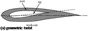
If a wing planform is tapered, for example, then the wing chord is different at each spanwise location, y0, of interest. This chord is denoted by c(y0). As noted previously, the induced angle of attack is generally different at each spanwise station of interest; hence, the notation, aj(y0) is used. If the wing has twist, then the geometric angle of attack, a, and the angle of zero lift, aL0 may be different at different spanwise stations, y0. There are two types of wing twist as follows: 1 [24]
Figure 6.12. Geometric and aerodynamic wing twist.

 transition from one section to the next would be smooth. Aerodynamic twist has the effect of making aL0 take on a different value at a different spanwise station of interest; that is, aL0 = aL0 (y0).
A wing may have geometric or aerodynamic twist or both, in which case the effects are added. The amount and type of twist are specified for a given wing. Wing twist is used to modify the spanwise-loading distribution over a wing planform. For example, Fig. 6.13 shows the distribution of bound-vortex strength or, by definition, Cl (see Eq. 6.19) along an untwisted wing of constant section with moderate taper. We notice in this figure that there are larger values of Г at some spanwise stations than at others. Thus, at about 60 percent semi-span, the local airfoil section is operating at a comparatively large value of aeff (see Eq. 6.14). The section at 2y/b = 0.60 is “working harder” than, say, the section at mid-span. Thus, as the geometric angle of attack of the wing is increased, the wing stalls first at about 60 percent semi-span. This may render ineffective a portion of a control surface or flap located near that spanwise station because it would be immersed partially in a “dead air” separated flow. Incorporating wing twist into the wing design could modify the spanwise distribution of aeff such that the wing would first stall farther inboard. An alternative method for tailoring the spanwise stall characteristics of a wing by modifying (i. e., “drooping”) the shape of the wing leading edge is in Abbott and Van Doenhoff (1959).
![]() Г/Г
Г/Г
![]()
 y/(b/2)
Fundamental Monoplane Wing Equation
This equation is written for a twisted wing of nonrectangular planform. It may be simplified as appropriate. First, by definition:
Next, substituting Eq. 6.13 into the expression for Cl in Eq. 6.12 and introducing the new notation:
Ci (Уо) = m H Уо b «i( УоЬ aL0 (%)]. (6.20)
Finally, we solve for a (for convenience):
a( Уо) = + a lo (Jo) + ai(Уо)
m0
 |
|
and substitute for CL(y0) from Eq. 6.19 and for ai(y0) from Eq. 6.15. The result is:
where the speed and chord distribution, то and aLo, are known for a given wing.
Eq. 6.21 is called the fundamental wing equation for a monoplane (i. e., for a single wing). This equation can be used to solve for Г(уо)—that is, for the distribution of bound vorticity—across the span. The solution process is not straightforward because Eq. 6.21 is an integro-differential equation for the unknown circulation strength.
The central problem of lifting-line theory is to determine the spanwise distribution of circulation—that is to find Г(уо) = Г(у)*—as a function of wing-shape parameters. If Г(у) can be found, L'(y) follows directly. Then, the wing total lift is given by the integration of L’ over the span, and the induced drag may be calculated from Eq. 6.18. Although circulation is not a physical variable, it is simplest to work with Г(у) as the unknown. Once Г(у) is found, the finite-wing problem is solved. A Fourier-series solution is discussed in the next section.


