YAW MOMENT ARMS
So far, only the development of lateral forces have been presented. Ultimately, a vertical tail surface is expected to contribute a stabilizing yaw moment, however. The arms providing such moments are discussed in the following, together with other means (fins) supplementing directional stability.
Vertical Tail Volume. The yaw moment produced by the vertical tail surface, can be expected to grow in proportion to both, area and arm (tail length). In coefficient form therefore,
dC^vldA = (dC^ldA )(Sи! S)0V lb) (18)
where the value of (dC^ /d^) primarily depends upon the shape (aspect ratio) of the tail surface. The term (Sy-ii/) has the dimensions of a volume. The vertical tail volume ratio
V/ ^/SHV/b) (19)
is thus a fixed characteristic of the airplane configuration.
Yaw Moment. A lateral force originating in the vertical surface, is expected to produce a yaw moment (“N” about the “normal” axis of the airplane) corresponding to
C* = “N”/qSb = ( – V/b) (V/S) = CjUl V (20)
When sideslipping, the derivative is expected to be
= dtyd* = (dC^/d* ) VK (21)
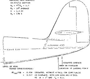
Within reason, both the lateral tail force and the yaw moment derivatives are independent of angle of attack and/or wing-lift coefficient of the configuration. Test data for yaw-moment contributions of vertical tail surfaces are given in figure 21. They increase essentially in proportion to the volume ratio provided by tail size and length. There is a difference, however, between the influence of length and vertical area. As explained in connection with figure 11, the lateral force derivative reduces somewhat as the length of the fuselage is increased. This influence is evident in figure 21, and it is marked accordingly.
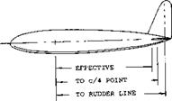
Moment Arm. One particular fuselage plus tail configuration is shown in figure 22. Dividing the derivative by that of the lateral force the effective moment
arm X/ is obtained, in the form of Xy/h. This arm is, of course, shorter than that measured to the rudder hinge line. However, the effective arm is also shorter (94%) than the distance of the quarter-chord point of the vertical tail surface from the reference axis (through the CG of the airplane for which the tests are undertaken). It thus seems that some lift is induced in the fuselage, somewhat ahead of the vertical tail’s root chord. This result is confirmed in figures 11, 12, 23, where the effective moment arms are between 3 and 8% shorter than the geometrical tail length (to the aerodynamic center point of the vertical surface). In terms of fuselage maximum diameter or tail root chord, the reductions listed are between 10 and 25%.
|
EVALUATION FROM L-17 (10,h) MEDIUM-LONG FUSELAGE WITH 9.7% S VERTICAL TAIL TESTED WITHOUT A WING, BUT BASED ON WING DIMENSIONS; TAIL CONTRIBUTIONS ARE: |
0.0032 0.0071
0.0032/0.0071
0.45 EFFECTIVE ARM RATIO 0.48 TO c/4 POINT OF TAIL
0.52 TO RUDDER HINGE LINE
Figure 22. Moment arms of the vertical tail of an airplane configuration derived from wind-tunnel tests (10,h).
|
Figure 23. Lateral force provided by the vertical tail surface of a fighteptype airplane (14,a). |
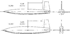
Fuselage Shape. The influence of the cross-sectional shape of the fuselage upon the directional characteristics is discussed in connection with the results in figure 4. The same series of bodies are shown in figure 24 combined with tail surfaces. The contribution of the vertical tail to the lateral force is essentially the same for the three fuselage shapes. The effective moment arms differ only slightly; they are all shorter than the geometrical distances to the quarter – chord line of the tail.
|
|
|
Rv = 5(10)5; TAIL DIMENSIONS AS IN FIGURE 12, ALTHOUGH DIFFERENT FUSELAGE, EVALUATED FROM TN 3857, FROM LATERAL FORCE Су. CROSS-SECTION AREA AND VOLUME OF THE FUSELAGE ARE KEPT CONSTANT. MOMENT ARMS IN (PARENTHESES) WERE OBTAINED WITH A WING PRESENT. |
Figure 24. Influence of fuselage cross-section shape uoon the lateral force and the moment arm of the vertical tail surface.
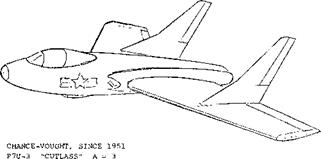
Fins on Top of the Wing. In tailless airplane configurations, some kind of vertical fin are required for directional stability. In swept-back configurations, a convenient place to attach such fins, is on top of the wing. Each fin of the airplane shown in figure 25 has an area equal to 9% of that of the wing. The geometric aspect ratio is = ha/S^ =1.5. There are two effects to be considered:
a) The wing can be considered to be a very large one-side end plate. The effective aspect ratio of the fins may thus be = 1.9 Ay = 2.8.
b) The pair of fins may interact with each other. For a lateral distance у = 1.9 h, or (y/h)(A//A^) = 1.0, figure 23 in the Chapter III (set up in terms of biplane interference) leads to the result that the effective aspect ratio is reduced from 2.8 to Af = 0.9 (2.8) = 2.5.
Using equation (14) the derivative of the lateral fin forces can be determined. It can be expected, however, that interference with the suction side of the wing will reduce the effectiveness of the fins somewhat (possibly by 10%). The moment arm (to the CG) available in the “Cutlass” configuration, is only ~ 1/4 of the wing span. To obtain the required stability, the combined fin area has to be larger than in a conventional configuration; it is 18% of the wing area in figure 25.
|
CARRIER-BASED FIGHTER VERTICAL SURFACES WITH: |
|
b |
= |
40 |
ft |
Sy = |
0.09 S |
|
w |
= |
27,000 |
lb |
ly – |
0.27 b |
|
Vx |
= |
580 |
lets |
VERTICAL |
TAIL VOLUME 0.05 |
|
PAIR |
OF |
JET ENGINES, EACH: |
30 to |
40 DEGREES SWEPT |
|
|
T |
= |
5,000 |
lb |
|
Figure 25. View of Chance-Vought F7U-3 “Cutlass” tailless airplane (25,c). |
(21) Influence of propeller power in fighter-type airplanes:
b) Recant, Curtiss XP-62 Model, W’Rpt L-779 (1943).
c) Goodson, Fleetwings XBTK-1, W’Rpt L-786 (1945).
e) Sweberg, Grumman XF6F-4 Directional, W’Rpt L-109
(1945) .
f) Sweberg, Load Distribution in Tail, W’Rpt L-426 (1944).
i) Purser, Rotation LW Airplane Model, NACA TN 1146
(1946) .
j) Johnson, V’Tail Modifications in Slipstream, NACA Rpt 973 (1950).
![]()
(22) Characteristics with dual-rotation propellers:
a) Neely, With Single and Dual Propeller, W’Rpt L-83 (1944).
b) Recant, Curtiss XP-62 Model, as in ref (22,b).
d) Wallace, Curtiss, XBTC-2 Model, W’Rpt L-787 (1944).
Twin Tails. Another type of fins is sometimes used in twin-engine airplanes. To facilitate handling on the ground, by keeping the rudders within the propeller slipstream, twin vertical surfaces can be attached to the ends of the horizontal tail, in the form of “end plates”. An example of this type of design is the Lockheed LI049, 749 “Constellation” airplanes. Results of a systematic wind-tunnel investigation on twin vertical surfaces, are presented in figure 46 which indicates that:
1) the effectiveness dC^/d^ increases with the aspect ratio,
2) shape “4” (straight trailing edge) is better than “3” (for the same aspect ratio),
3) there are discontinuities in two of the shapes investigated,
4) the type of surfaces tested, is effective up to= 30 and possibly 40 .
 The discontinuities mentioned seem to be caused by flow separation on one side where the horizontal tail interferes with the suction side of the vertical surface. The high angles permissible, are simply a consequence of the low aspect ratios used.
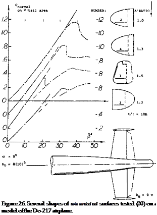
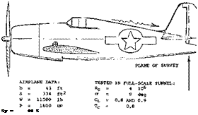
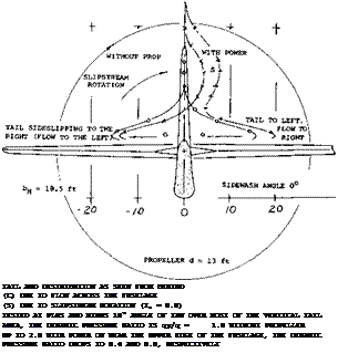
Figure 27. Results of wind-tunnel tests (21,e) on the Grumman F6F fighter-type airplane, showing the distribution of sidewash at the location of the vertical tail.
(23) Lateral characteristics of high-wing airplanes:
a) Hagerman, HW Airplane w’Power & Flaps, NACA TN 1379 (1947).
b) Same model in low wing arrangement, see Tamburello, NACA TN 1327.
c) Longitudinal characteristics of same models, TN 1239 and 1339.
d) McMillan, “Puss Moth”, ARC RM 1794 (1937); also Batson, RM 1631 (1935).
e) Paulson, Fighter in Inverted Flight, NACA W’Rpt L-15 (1945).
(24) Lateral directional characteristics of jet-propelled airplanes:
a) Brewer, Bell P-59 in Full Scale Tunnel, W’Rpt L-626 (1945).
b) NACA (Douglas) X-3 research airplane: Flight-test results, Bellman, NACA RM H54I17. Wind-tunnel tests on very similar model, NASA Memo 1-22-59L.
c) A single tail-jet and a twin jet (in the wing) airplane are reported by Davis, Effect of Jet on Stability, NACA W’Rpt A-31 (1944). The “changes in directional stability and trim are negligible”.
![]()
The influence of propulsion system on the directional characteristics of an airplane is dependent on the forces and moments produced when operating at an angle relative to the flow. In addition the slipstream and the induced effects of the propulsion system can produce important interaction effects that will influence the results. Propeller driven airplanes produce large forces and moments when operating at an angle of attack and have a large slipstream which often infringes on the aerodynamic surfaces of the airplane as discussed in Chapter XII. Although few new propeller aircraft are being designed and built the influence of propellers are covered as this will serve as a basis for the systems using jet propulsion, especially with the trend toward much higher by-pass ratio. This is desirable as considerably more data is available on the subject of propellers than for jet systems.
|
|
|
POWERED MODEL OF A SINGLE-ENGINE LOW-WING AIRPLANE: |
|
d |
0.3 |
b |
|
Sp = |
.53 |
S |
|
T |
0.5 |
L |
|
Rc =: |
1 ■ |
• 10* |
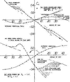
Figure 28. Yaw moments of a low wing airplane configuration (14,a) in cruising condition:
(A) with propeller windmilling
(B) with full power on Tc = 1.0.
The normal forces originating in propellers when at an angle of attack are explained in the Chapter XII. The same type forces are also obtained when sideslipping due to the angularity of flow into the disk.
Tractor Propeller. The propeller of single-engine airplanes (such as the fighters, for example, in figures 27 and 28) may have:
a solidity ratio S^ /Sp =10% a “0.7” blade angle “/?” = 30 a disk area d‘V /4 Sp = S/3
a moment arm to CG = b/4
Using the derivative dC^ /d^ = 0.035, as found in Chapter XII the lateral force may correspond to
Суз/5 “ (dCNS Id# ) (Sg /Sp) (Sp/S) –
0.035 (0.3)/3 = 0.0012 (31)
and the yaw moment due to the normal force of the propeller may correspond to
Сфр = – dCy/zp (Jp/b) = – 0.0012/4 = -0.0003(32)
For comparison, the derivative due to the fuselage may be in the order of — 0.0001, and that due to vertical tail up to + 0.0010. So, the propeller-force moment is usually the most destabilizing single component of any powerful (tractor-type) single-engine airplane configuration, such as fighters in particular.
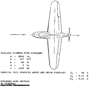
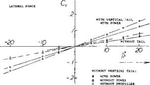
Pusher Propeller. Directional characteristics of a “tailless” airplane configuration are shown in figure 29. While a pusher propeller at the end of a fuselage is an unusual arrangement, the results promise to shed light on the interaction between this type of propeller and the wing or a vertical tail located ahead.
The yaw moment of the wing fuselage combination displays the usual destabilizing moment due to the fuselage.
The addition of a vertical tail (“double”, above and below the fuselage) stabilizes the yaw moment..
When adding the windmilling propeller (no thrust) the normal forces originating in the propeller blades increase directional stability, propeller fin effect (19).
Finally, when adding power to the configuration, a maximum of directional stability is obtained.
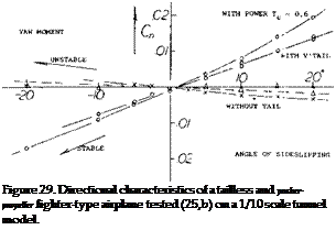 The propeller slipstream is the consequence of a pressure increment Л Cp = Tc, across the propeller disk. The average increment (v) of the speed “in” the disk is theoretically
V// = 0.5 VTTt; (22)
Where Tc = the propeller thrust coefficient = T/qSp. Full speed, corresponding to twice this increment, is theoretically reached at some distance (say beyond one diameter) behind the propeller. As far as the flow ahead of the propeller is concerned, the disk represents a “sink”, into which air is attached from “all” sides. Only a small influence can expected, accordingly, of the propeller upon the vertical tail surface located ahead of it. Equation (22) suggests, on the other hand, that normal force in the, and yaw moment contribution of the propeller proper, be increased, for example by 40% for Tc = 1. Results plotted in figure 29 show an effect somewhat stronger than according to this reasoning. The added increment must be due to the influence of the propeller (suction) upon the tail surface.


