Aerofoil section design
5.2 Twodimensional aerofoil sections have received much attention from the beginning, partly because they are so much easier to deal with than threedimensional wings. Also, some useful design guidance could be gathered from exact solutions, obtained by the method of conformal transformations, such as the series of Joukowski and Karman-Trefftz aerofoils. For many decades, the aircraft designer did not conceive his own aerofoil section but consulted one of several well-known catalogues, in which (often hundreds of) section shapes and some of their main aerodynamic characteristics were listed, in the hope of finding one that suited his purpose. This procedure is now generally acknowledged to be inadequate; it has been replaced by that outlined above, which may be illustrated here by a very simple example.
![]() LIVE GRAPH
LIVE GRAPH
 |
Click here to view
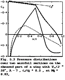
Consider the design of a svibcritical aerofoil section to give certain values of the Mach number and of the lift coefficient on the sheared part of a tapered wing of moderate sweep and let the pressure distribution be of the rooftop type, as in Fig. 5.2 (see D KUchemann (1968)). This means that the pressure over the upper surface should follow the critical pressure from the nose downstream to a certain point and that it should then rise in such a way that separation is just avoided. The nose shape may depart from that giving a roof-top distribution and be modified and adapted to give better off-design behaviour, at supercritical conditions, say, or at low-speed high-lift conditions. A great variety of pressure distributions over the lower surface can now be drawn which all fulfil the condition that the sectional lift coefficient should have a given value. Two such curves are shown in Fig. 5.2 (where, for
simplicity, some unrealistic kinks have been allowed in the curves). One is a mild case, as far as adverse pressure gradients and isobar sweep are concerned; the other is a severe case, with a large amount of rear loading*), where the suction peak on the lower surface is almost as high as that on the upper surface so that the problems associated with isobar sweep on threedimensional wings and with adverse pressure gradients are probably more severe on the lower than on the upper surface. The main distinction between the two resulting shapes is that they imply different thickness-to-chord ratios: the section with rear loading is thicker but has a smaller trailing-edge angle. This example demonstrates not only that such design calculations can readily be carried out but also that they do not provide enough information to make a definite choice: before a rational decision can be made, consideration must be given to many other repercussions, such as off-design conditions, the questions of how the section may be designed effectively into a threedimensional complete wing and how variable-geometry devices may be incorporated, and the structural implications. For instance, it is not immediately apparent whether the greater thickness of one section can be exploited to make a lighter wing.
The example in Fig. 5.2 has been calculated by the RAE Standard Method. For incompressible flow, an alternative is to use the hodograph method for designing twodimensional aerofoils to have prescribed pressure distributions. This has been applied by К Mangier (1938) and by M J Lighthill (1945), starting from the aerofoil theory of S Goldstein (1942) to (1945). This method has been extended by various authors, and T Strand (1973) has devised a practical way of modifying a given pressure distribution so as to ensure that the resulting contour is closed at a sharp trailing edge. Strand also demonstrated how a roof-top section can be designed where the turbulent boundary layer in the adverse gradient over the rear portion of the upper surface has the zero-skin – friction profile of Stratford, for a given Reynolds number. In many practical cases, any difficulties with the closure condition are avoided by prescribing the thickness distribution and determining only the camber line to give a certain pressure distribution over the upper surface.
Of practical interest is the design of aerofoil sections to have relatively large regions of controlled supercritical flew over the upper surface (see Fig. 4.8). An example of early design work by H H Pearcey (1960) has already been shown in Fig. 4.62. This work has been continued and experience built up on the geometrical properties having favourable supersonic flow characteristics, as described by R C Lock & J L Fulker (1974). Some of the methods discussed in Section 4.8 can also be used for design purposes, such as the MLR hodograph method for shockfree flows, or the panel method by F T Johnson &
P E Rubbert (1975). The method of J Sato (1973) uses integral relations and quasi-linearisation and has the advantage that singularities at stagnation points are removed analytically. The various TSP-methods can be inverted for design purposes, such as the RAE TSP-Method or that by J L Steger & J M Kline – berg (1973), which allows alternation between inverse and direct calculations to obtain a profile shape that satisfies given geometric constraints. A TSP – method which has been applied successfully is that by M J Langley (1973), which has been extended by E Stanewsky & H Zimmer (1975). Like many other methods *) As an alternative, rear loading can, of course, be obtained also by small deflections of a trailing-edge flap (see Section 4.7). This may be used to unload the front part of the wing for a given lift, whenever that is beneficial, and this has been successfully applied on some actual aircraft, e. g. on some early versions of the DC 8 aircraft. Thus "rear loading” should not be regarded as a magic new "invention".
of this kind, it is restricted to the modification of existing авто foils. The required velocity distribution is obtained by an iterative process which converges quickly only when successive forward calculations are made with regular updating of the aerofoil shapes. H Sobieczky (1975) has designed supercritical aerofoil sections with the aid of the rheoelectrical analogy. What has been achieved so far is typically a drag-rise Mach number of 0.8 at a lift coefficient of 0.5 on an aerofoil with t/c =0.1 (which is quite satisfactory when compared with the results in Fig. 4.61). In most cases, the local Mach number has not exceeded about 1.2 (as in Fig. 4.56). All the designed aerofoils have a certain family resemblance and look like the full line in Fig.
5.2, except that the front part of the upper surface is flatter, like that of the thin symmetrical aerofoil in Fig. 4.56. It may be expected that further substantial improvements can be made by going to higher local Mach numbers and stronger shockwaves which lead to flow separation and reattachment, as in Fig. 4.64(b). But there is as yet no method to deal with, and to design for, such flows, and future developments may have to rely even more on experiments which, in turn, may be beset with the difficulties of measuring and interpreting the effects of viscosity, as explained in Section 4.8. These have already shown up in existing experimental results by L H Ohman et at• (1973), J L Fulker
(1974) , P G Wilby (1974), and E Stanewsky & H Zimmer (1975).
The examples just described are frequently encountered in conventional wing design. We turn now to some more unconventional design possibilities which have hardly been used in practical applications. These will give some insight into fluid-motion problems, but some may also be found useful in future.
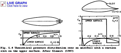
M J Lighthill (1945), M В Glauert (1945) and (1947), and J Williams (1950) have designed twodimensional aerofoils which incorporate suction through a slot as an essential device. There are many other investigations into this kind of boundary-layer and flow control (see e. g. G V Lachmann (1961)), and Prandtl demonstrated already in 1904 that suction produces a sink effect which can usefully be applied to aerofoils which would otherwise have too steep an adverse pressure gradient for the flow to remain attached: "If the drop from the summit to the foothills is replaced by a shear precipice, by a discontinuity in
Fig. 5.3 Theoretical pressure distribution over a lobsterpot aerofoil with suction at the trailing edge. After Glauert (1947)
fact where the boundary layer is sucked away, and the remainder of the velocity curve given an even declivity down to the trailing edge, it is to be hoped that breakaway will be avoided" (Lighthill (1945)). Two results of this work are shown in Figs. 5.3 and 5.4,refined to a point where the pressure along the upper surface is kept constant, or piecewise constant. This leads to uncommonly thick aerofoils for a given lift, and the absence of any adverse pressure gradient also offers the possibility of keeping the boundary layer laminar. On the whole, experiments by T S Keeble & P В Atkins (1951) have confirmed the theoretical results in Fig. 5.4, although the details of the slot design presented difficulties. This kind of problem is brought out clearly in the simpler case of the lobsterpot aerofoil in Fig. 5.3: a free stagnation point must exist near the slot intake, and the air is not really "sucked" into the slot but "pushed in" by the high pressure near the stagnation point. Such a flow is not normally steady, but D M Heughan (1953) has shown that the flow may be stabilised by introducing a solid plate along part of the streamline in the line of symmetry, upon which the stagnation point can rest. No difficulties will arise from the boundary layer formed along this plate, as the flow is accelerated both ways. In principle, any such slot should be regarded and designed as an air intake, and it would seem necessary to take account also of the fact that much of the air taken in is in a shear flow. This intake problem has not yet received any attention. Note that the constant-pressure shapes and the lobsterpot, in particular, are closely related to the shapes of cavitation bubbles behind solid bodies (see e. g. G Birkhoff & E H Zarantonello (1957) and L C Woods (1961)).
 |
|
The line of thinking behind the lobsterpot aerofoil can be pursued further and lead to various possible types of aerofoil sketched in Fig. 5.5. Case (a) shows a ducted aerofoil with reverse flow inside (see D Ktichemann (1954)). The air which emerges from the duct at its front end divides into two streams which turn around the two parts of the aerofoil (which need not be symmetrical, as in Fig. 5.5, but would have different shapes on a lifting aerofoil); these streams join again when they enter the rear end of the duct. This air circulates permanently around the two halves of the aerofoil, and it is separated
from the external flow by a dividing streamline which encloses the whole body. This streamline now has two free stagnation points. The front part of the aerofoil can be designed so that the flow along the wall of the duct accelerates and that the pressure then stays at a prescribed constant value from where the wall begins to curve. Such shapes have been calculated, using the hodograph method, by E Eminton (1960) for semi-infinite bodies where the curved nose is followed by a cylindrical part (further work and applications of this kind of flow will be discussed in Section 8.4). Complete shapes, especially lifting aerofoils, of this kind have not yet been calculated, but we can expect that the uniformity of pressure, at least over the upper surface, will lead to relatively thick aerofoils with relatively high critical Mach numbers and possibly laminar flow, for a given lift. Perhaps more importantly, we note that it must be possible to arrange the flow in Fig. 5.5 (a) in such a way that no viscous wake is left behind. Work must then he done on the viscous flow inside the duct to add energy to it and to keep it moving, but the power required to do this may be less than that needed in a conventional propulsion unit which processes mainstream air. These fundamental propulsion problems have been considered by A M 0 Smith SHE Roberts (1947) and J В Edwards (1961).
Case (b) in Fig. 5.5 shows a jet wing, again with a duct through the aerofoil but with the flow in the same direction as the mainstream (see D KUchemann (1944) and D KUchemann & E C Maskell (1956)). A certain mass of air now enters the wing at the intake in the leading edge and is ducted to some device which can supply energy to the air. This could be a turbojet engine with bypass fans, where the bypass duct is not annular as in conventional fan engines but divided into two cold-air ducts on either side of the gas generator. Such a flat engine can be more readily integrated into the wing, and the jet wing thus combines the generation of lift and thrust. This may be more efficient than the conventional Cayley-type arrangement of isolated engine nacelles installed somewhere outside the wing or fuselage, especially when the diameter of the conventional fanjet engine is comparatively large so that large interference forces (and hence drag losses) are unavoidable. The jet wing with a large number of fans must have some duct losses instead. To keep these small requires relatively low duct velocities and lightly-loaded fans. This, in turn, implies a relatively large size and low jet velocities, which should lead to good Froude efficiencies and low noise. No detailed assessment of this scheme has yet been made.
There are other similar pneumatic, or powered, schemes, intended mainly to generate high lift (see e. g. J von der Decken (1970), G К Korbacher (1974)).
The augmentor wing, where use is made of the injector effect by blowing into a duct, is mentioned especially (see also D C Whitley (1967) and В M Spee (1975)).
By contrast to these schemes, case (c) in Fig. 5.5 involves a strong, high-velocity thin jet sheet. In the example shown, the jet emerges tangentially from a slot somewhere upstream of the trailing edge of a small (deflectable and possibly retractable) flap and remains attached to the wall by virtue of the Coanda effect (see e. g. R Wille & H Fernholz (1965)), so that it leaves the trailing edge tangentially at an angle to the mainstream which can be varied. The air in the jet may be supplied by a high-bypass-ratio turbojet engine and ducted through the wing. The jet will curve back into the mainstream direction and thus, in principle, all the thrust should be recovered.
The main physical feature of this flow is that there is now a significant pressure difference across the curved jet and hence also at the trailing edge.
This is a fundamental effect: the Kutta condition of smooth outflow from the
trailing edge for a curved jet implies a pressure difference and thus a load at the trailing edge. This goes together with an induced circulation around the aerofoil and hence a lift force.
This jet flap ‘ has been investigated first by H Hagedom & P Ruden (1938) and then again by I M Davidson (1956), by L Malavard, Ph Poisson-Quinton & P Jousserandot (1956), A Das (1960), J von der Decken (1971), A В Bauer (1972),
N D Halsey (1974), and С C Shen et at. (1975). The physical features of the flow were largely clarified by E C Maskell & S В Gates (1955) and D KUchemann (1953) and (1954), and D A Spence (1955) developed the basic linearised theory for the twodimensional jet flap, assuming perturbations to be small. Experimental work carried out at that time by N A Dimmock (1955) , J Williams &
A J Alexander (1955), and L Malavard et at. (1956) largely supported the theoretical concepts and results. A jet-flap research aircraft, the Hunting H 126 (see J W R Taylor (1963/64) and К D Harris (1970)), was built and flew successfully from March 1963 onwards. This aircraft has been flown at lift coefficients up to 7.5 and a maximum usable CL of about 5.5 has been established, the limitation being determined by the lateral control characteristics and the need for an adequate margin below the extremely sharp stall. These matters have been investigated experimentally and theoretically, e. g. by S F J Butler et at. (1961) and by H H В M Thomas & A J Ross (1957). A comparison between results from windtunnel and flight tests has been made by D N Foster (1975).
Spence’s theory for the tuodimensionat jet flap in incompressible inviscid flow is an interesting example of the application of the concept of linearisation. The accepted methods of thin-aerofoil theory are used; the jet-deflection angle t is assumed to be small (but close agreement with experimental results is obtained up to values of т as large as 60°); the jet is assumed to be infinitely thin but to have a finite momentum flux J. That is, if 6 is the jet thickness and Vj its mean velocity, it is assumed that J =pjVj6 is finite and constant along the jet, and equal to ІРо^О^4jC as 6 -*■ 0.
Here,
CT = — (5.1)
5povo2c
is the jet momentum coefficient (sometimes denoted by ) and pq and p. are the densities of the undisturbed stream and of the jet, respectively. JIt can then be shown that the jet with a local radius of curvature R can sustain a pressure difference
Ap = J/R or ДСр = Cj/(R/c) . (5.2)
The jet can now be represented by a single vortex sheet of the strength
*)
The term jet flap came about when it was thought that there was a strict analogy between a mechanical solid flap and the jet effects discussed here. This is only partly justified in the general sense that any vorticity downstream of an aerofoil may induce a lift on it (see Section 4.7), but otherwise the analogy is questionable and not helpful. The term is retained here because it is now in general use.
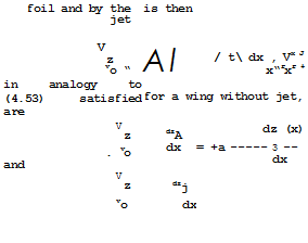
by (5.2), if the shape of the jet is given by z = zj(x) for x £ 1, with the aerofoil chord taken as unity. It is then assumed that this vortex distribution can be placed on the continuation of the chordline (z = 0), instead of on the trace of the real jet, together with the distribution Уд(х) of bound vorticity representing the main aerofoil. The downwash induced by the aero-
![]()
![]()
![]()
![]() ‘J dx’
‘J dx’
2 x – x’
The boundary conditions to be
(5.6)
![]()
 |
||
where zc(x) is the shape of the camberline of the aerofoil.
![]() – 7- g(x)
– 7- g(x)
CJ
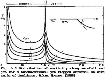
Spence solved these equations by Fourier analysis for uncambered aerofoils, for given values of a, Cj and т = dZj/dx at the trailing edge. Typical results for the vorticity distributions along the aerofoil and along the jet are shown in Fig. 5.6. There is some resemblance with the results in Fig.
4.46 for a thin plate with deflected flap. In particular, the load is infinite at the trailing edge as a consequence of the sudden change in flow direction.
The lift on the thin uncambered jet-flap aerofoil can be divided into two parts one proportional to the jet deflection angle т and the other proportional to the angle of incidence 01 :
CL = A(Cj) t + B(Cj) a . (5.9)

the following approximations for the coefficients
 |
|
The Aerodynamic Design of Aircraft
These may be used for Cj-values up to about 10. The lift force according to
(5.9) acts in the form of pressures along the surface of the aerofoil. There is also a corresponding tangential force component associated with the generation of lift:
CT = – Cj(l – cos t) (5.11)
according to E C Maskell & S В Gates (1955). A remarkable feature of this flow is that lift can be generated even when the aerofoil is at zero angle of incidence.
The theory for threedimensional unswept wings of high aspect ratio has been extended to cover the jet flap by E C Maskell (1955) and by E C Maskell & D A Spence (1959). The main result of this theory is that, for a given lift, the induced angle of incidence on the wing is reduced by the blowing:
cL
a. = —- *47- (5.12)
1 тгА + 2C

![]() The effectiveness of the jet as a lift augmentor is also of the finite span. At a given lift, the vortex drag is a plain wing, according to
The effectiveness of the jet as a lift augmentor is also of the finite span. At a given lift, the vortex drag is a plain wing, according to
![]() Sv
Sv
which is to be compared with (3.22) for a plain wing, to the same approximation. The total drag force on the threedimensional wing can then still be written as
CD " CDF + CDV * (5Л4)
in analogy to (3.42). Analysis of the experimental evidence suggests that, as on plain wings, the viscous friction and form drag C™ is roughly independent of aspect ratio and angle of incidence, provided that significant flow separations on the wing are avoided. More recent developments in threedimen
sional jet-flap theory have been reported by M L Lopez & С C Shen (1971) , С C Shen et at. (1975), and PBS Lissaman (1974).
Another model of the flow past jet-flapped wings is even simpler but may help to explain some of the physical features and give some pointers to how such wings should be designed to make full use of the principle (see D KUchemann (1956)). We describe it here because the main effects are likely to occur again in any scheme which involves jet blowing from somewhere near the trailing edge of a wing. This model is related to the Thwaites flap (see В Thwaites (1947)), which is a small thin flap in contact with and roughly perpendicular to the lower surface of an aerofoil with a rounded trailing edge, which fixes the position of the rear dividing streamline, provided some form of boundary – layer control maintains a thin unseparated layer. In the case of an aerofoil, the boundary layer could be kept attached through the very steep adverse pressure gradient between the high suction at the trailing edge and the stagnation point by suction or blowing or by some kind of entrainment mechanism. When the Thwaites flap was applied to a circular porous cylinder with distributed suction, R C Pankhurst & В Thwaites (1950) found it worked well and attained a lift coefficient of nearly 9. Now, a jet emerging near the trailing edge may fulfil the same function as the Thwaites flap by fixing the rear stagnation point and hence the circulation, increasing the circulation beyond the value it has when the stagnation point is located at the trailing edge. In this model of the flow, the vorticity along the jet is ignored and, for a given overall circulation, the loading over the aerofoil must then be such that the downwash it produces compensates only the vertical velocity component of the mainstream. There may be a load on the aerofoil even when it is placed along the mainstream direction, i. e. lift can be produced independently of the angle of incidence, as in the more complete model of Fig. 5.6.
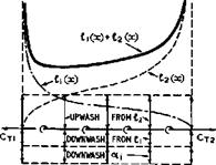
To explain this fundamental mechanism further, consider the simple case of a twodimensional flat plate at zero angle of incidence with a jet emerging from the lower surface at a point just upstream of the trailing edge. If the jet fixes the circulation in the manner of a Thwaites flap, then the flow and hence the loading must have fore-and-aft symmetry. It must also be such that no upwash or downwash is induced, i. e. v =0. Thus the loading l(x) along the chord may be regarded as the sum of two parts, Jlj(x) + ^(x)» one inducing a constant downwash and the other an equal and opposite upwash. From (4.53) and (4.54) such solutions are known:
Я(х) – Я,(х)+Я2(х) – • (5Л5)
i. e. we have two flat-plate distributions, back to back to each other, as indicated in Fig. 5.7. This explains the saddleback loading distribution which is typical of twodimensional jet-flap aerofoils, even in cases like that in Fig. 5.6 where the jet emerges from the trailing edge. There are suction forces at both leading and trailing edges, which are equal and opposite in twodimensional flow:
since С^д ■ Сд2 (see (3.30)). In this approximation, the thrust associated with the jet does not appear in the form of pressures along the outer surface of the aerofoil: it must act inside the hypothetical duct from which the jet emerges. However, the theory can be extended to include the thrust from (5.11)
 |
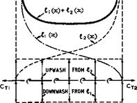 |
Fig. 5.7 Distribution of bound vor – Fig.5.8 Distribution of bound vor – ticity and of downwash along the chord ticity and of downwash along the chord of a twodimensional aerofoil with jet of a threedimensional wing with jet flap flap
(D KUchemann (1956)), in which case fore-and-aft symmetry is no longer maintained, But this effect is usually small unless Cj is very large.
This flow model readily explains what happens on a threedimensional wing of high aspect ratio. Consider again a flat wing at zero angle of incidence, as in Fig. 5.8. Within the framework of the approximate theory described in Section 4.3, there is a downwash induced by the trailing vortices, which is
 |
|
constant along the chord and given by (5.12). This means that the downwash induced by the loading A^(x) can be reduced by the same amount to keep the overall downwash zero. Hence, £^(x) can be reduced correspondingly, and the result is that the chordwise loading becomes asymmetrical, the front of the wing being unloaded. The suction force CTj at the leading edge is then also reduced; it is smaller than the suction force CT2 at the trailing edge by an amount which is equal to the vortex drag (5.13). The symmetrical saddleback loading can only be restored in the special case of a wing of high aspect ratio with a weak jet (where Cj « тгА/2) when the jet-induced thrust is equal to the vortex drag.
This approximate theory is of a form which can readily be extended to cover all the significant effects of thickness, finite span, compressibility, and sweep, as for wings without jet. It can also be used for design purposes, e. g. by incorporating camber to reduce the high suction peaks near the leading and trailing edges and to make the loading more uniform. The methods of A В Bauer (1972) and N D Halsey (1974) can also be used for design purposes. Thickness and camber distributions are determined separately, and examples have been given which have only very small regions of adverse pressure gradient.
![]() LIVE GRAPH
LIVE GRAPH
 |
Click here to view
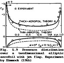
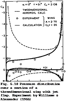
Two examples in Figs. 5.9 and 5.10 demonstrate the effect of thickness on a twodimensional aerofoil and the effect of finite span, for incompressible flow. Experimental results are also shown, and it will be seen that the simple theory reproduces the main features quite well, bearing in mind that viscous effects must also play a part, especially in the region of the jet exit. Note that the stagnation pressure is never reached near the trailing edge in the experiments, although very large adverse pressure gradients are overcome. These examples also show quite clearly that, although a jet can have a powerful effect on the flow, wings must be specially designed to make full use of this effect: just blowing out of a conventionally-shaped wing is not sufficient and produces loadings which are still highly non-uniform. On the other hand, it is also clear that jet-blowing could be an efficient means for integrating the generation of lift and of thrust and also for overcoming the fundamental conflict between low-speed and cruise designs of classical and swept aircraft: it could be applied throughout the whole flight range.
Complete designs of this kind, which would also take account of the nozzle flow and of all the lift, thrust, and drag forces cannot yet be carried out on the
basis of the available theories. Besides, these are in some sense contradictory and thus make it difficult to decide how the design aims should be achieved: Should one aim at pulling the rear separation point round to the lower surface, as the Thwaites-flap model would suggest (where the "flap" itself takes no pressure difference) ? Or should one aim at a highly-curved jet emerging from the trailing edge itself and thus maintain a large pressure difference there? The two approaches also require different shapes: in the first case, the trailing edge should be rounded; in the second case, it should be sharp. Existing experimental evidence is not clear enough to decide which of the two courses is to be preferred.
Kuchemann (1956) has advocated blowing over a small movable flap, as in Fig. 5.5 (c), as a potentially useful application of the principle, which could lead to an orderly and efficient flow, with separation lines firmly fixed at the sharp edges of the nozzle and of the flap. For the jet flow between nozzle and trailing edge, existing information about wall Jets can be used (see e. g. the review papers by R Wille & H Fernholz (1965) and by H Fernholz et aim
(1970) ). Wall jets are usually thought of primarily as means of boundary – layer control to keep the flow attached up to the trailing edge. Here, we want to go further than that and also exploit the jet-flap effect so that the circulation is greater than the natural Kutta circulation, i. e. we want to achieve what is sometimes called зирегеггсиїаЬгоп. This scheme has not yet been worked out in any detail. In any jet-flap scheme, the effect of air entrainment into the jet must be taken into account. This may lead to thrust losses, as has been shown by I Wygnanski (1966). More complicated propulsive-lifting systems have been evaluated by Ya-Tung Chin et aim (1975). R C Lock & С M Al – bone (1971) have proposed an extension of SpenceTs method to make it suitable for design purposes, but results are not yet available. One could try to design aerofoils with pressure distributions like that sketched in Fig. 5.11, i. e. the roof-top distribution of Fig. 5.2 for subcritical flow might be con-
|
Fig. 5.11 Sketch of possible camber line and pressure distribution for a jet-flap design |
LIVE GRAPH
Click here to view
tinued to end right at the trailing edge. The additional loading required would then be quite different from the saddleback loading of flat wings with jet and thus the aerofoil would have to be cambered. The camber line needed might be of the kind sketched in Fig.5.11. Similar design aims might be per – sued at supercritical speeds, where the pressure difference across the jet at the trailing edge might be used in flows like those in Fig.4.58 to extend the supersonic region rearward and, if possible, to place the terminating shockwave at the trailing edge. Such flows have not yet received any theoretical treatment.
Tests on twodimensional jet-flapped aerofoils up into the transonic flow regime have been carried out by H Yoshihara et at. (1971), W E Graham et
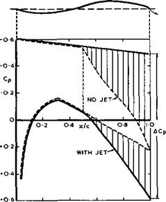
at. (1971) and H Yoshihara et at. (1973). Tests done at ONERA by Ph Poisson- Quinton (1973-,- unpublished) show that the jet thrust can indeed be fully recovered up to high-subsonic Mach numbers, but that the efficiency deteriorates when the critical Mach number is exceeded substantially. We reproduce here, in Fig.5.12, some pressure distributions measured by H Yoshihara et at.
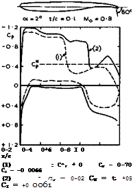 LIVE GRAPH
Click here to view
Fig. 5.12 Experimental pressure distributions over a twodimensional aerofoil with jet flap. After Yoshihara et al. (1973)
(1973) on a typical supercritical aerofoil not designed for jet blowing. Some of the expected jet-flap effects can readily be detected, but closer inspection reveals that the efficiency of the blowing is lower than it could be. Clearly, aerofoils must be specially designed to make full use of the principle.
An interesting variant of the jet-flap scheme has been proposed by A M 0 Smith & J A Thelander (1974), The aerofoil has a blunt rounded trailing edge, and separation is avoided by two wall jets, one above and one below, at the beginning of the pressure rise near the trailing edge. Blowing is used at all times, and these aerofoils are, therefore, called power profiles. Preliminary investigations and tests suggest the following tentative advantages: high wing thickness (perhaps 15%) and hence low wing weight and high wing volume; a simple high-lift system with high lift coefficients in the power mode (typic-
ally about 8 at Cj = 1 and a = 0) and low pitching moments; simple lightweight controls with rapid response, which may be used as manual controls for large aircraft or for active control systems to give improved manoeuvrability; a boundary-layer control mode of operation; the possible use for thrust reversal; and reduced noise. On the other hand, the internal ducting may present engineering difficulties; the thrust recovery may be poor in the power mode; and the control effectiveness may be weak in the boundary-layer – control mode. Nevertheless, the advantages of this scheme are so promising that further explorations are desirable. It may turn out to be the most practical way of applying the jet-flap principle.
There are many devices designed to increase lift, especially at low speeds. These matters have already been discussed in Section 4.7. We mention here only, in addition, solutions obtained by К Gersten (1973) for flows with strong blowing or suction rates, which might be applied in aerofoil design. There are also accounts of rational design methods by A M 0 Smith (1972) and
(1974) and by F X Wortmann (1972), and a detailed description of the design of an aerofoil to obtain high lift has been given by G J Bingham & Wen-shin Chen (1972).
One drawback of most devices to overcome the conflict between low-speed and cruise designs is that they operate well only at their own design point and that they cannot be continuously varied so as to be adapted for various flight conditions. This drawback may be remedied by variable-geometry devices which involve flexible surfaces. Some of these will be briefly described.
|
FLEXIBLE SKIN T
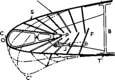
Fig. 5.13 Sketch of variable aerofoil mechanism (RAEVAM) |
The first device is a mechanism to change the shape of the leading edge continuously and smoothly, within certain limits, to improve the high-lift performance over a wide range of speeds. It is an alternative to a leading – edge slat as shown in Fig. 4.47 and, since these have many problems of their own and require some compromises to be made over the speed range, the flexible mechanism should potentially offer some improvements even though the beneficial effect of a slot can no longer be exploited, at least not without much greater complications. This RAE Variable Aerofoil Mechanism (RAEVAM) is sketched in Fig.5.13. It is based on a mechanism originally proposed by D Pierce (1965) for flexible supersonic nozzles in windtunnels and has been described by G F Moss et al. (1972). It is a linkage system within the wing. A small part of the leading edge is left solid and is constrained by the arm (A) to rotate about some point P fixed to the airframe. The rest of the skin is flexible and constrained in shape by means of a series of links
pivoted at the inner side of the skin at one end and at various points on an extension to the main spar at the other. The ends of the flexible skin slide in sealed joints where they blend with the fixed part of the wing profile.
The variation of the leading-edge shape is achieved by means of a single jack (J). Three shapes of the leading edge may be specified precisely, and these determine the lengths and pivot positions of the links. The changes of shape between these design points are always smooth and progressive. Of the three design points, that with the largest droop could be chosen to give high lift at low speeds and the other two could possibly meet particular requirements of high-lift performance at high speeds. Fig.5.13 shows only the simplest mechanism of this kind. Other variations are possible, which give more freedom in the design: the mechanism can be adapted to vary along the span;
and it can be applied to parts of the wing other than the nose. How much it it can be exploited in practice is not yet known.
The RAEVAM mechanism can, of course, be used in such a way that the nose is turned into the direction of the attachment streamsurface and that the attachment line itself is always placed near the point of highest curvature of the section, for a range of Cx,-values. The curvature of the flow along the upper surface is then reduced and with it the suction peak. Similar effects can be obtained by the Krttger flap (see W Kruger (1943)). This is a thin flap with
|
|
|
|
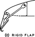
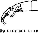
Fig. 5.14 Two possible arrangements of a Kriiger flap. After Wimpress (1972)
a slightly rounded leading edge, hinged near the leading edge of the wing, which, when undeflected, rests within the lower surface of the wing, as sketched in Fig.5.14 (a). When operational, it can be deflected so that it catches the attachment streamsurface and that the attachment line rests on the leading edge of the flap. If the Kriiger flap itself has some built-in flexibility, as in some recent applications (see J К Wimpress (1972)), the curvature of the new upper surface can be made smooth and continuous, as sketched in Fig. 5.14(b). This can be an effective means of keeping the leading-edge flow attached up to higher CL-values than on the original aerofoil. It has proved itself in flight. Note that the lower surface is partly left open and un
faired, hut this does not seem to matter much in the high-pressure region generated there at high lift.
 |
Another application of variable-geometry concepts in aerofoil design by F X Wortmann (1970) is shown in Fig.5.15. In this case, the chord is extended substantially and an overall camber of about 10% incorporated. To achieve
a smooth shape, part of the surface must be flexible. This scheme is an alternative to a Fowler flap as shown in Fig.4.47 and, again, a slot is not used. This particular device has been specifically designed for gliders and has been fully engineered and applied in the Sigma sailplane (see N Goodhart
(1969) ). As already mentioned in Section 4.1, the aerodynamic design of gliders is particularly demanding. There are three different main design conditions to be satisfied during various modes of flight: to achieve a very
low drag and hence to reach a high speed at relatively low (^-values; to reach a high lift-to-drag ratio so as to achieve a low glide angle; and to reach a high rate of climb at relatively low speeds, i. e. to achieve a high value of the parameter. The first two requirements should be
satisfied without changing the geometry of the wing; the last can more readily be fulfilled by a change of shape. The problem is then to find two aerofoils which perform well at both high and low speeds, and which are geometrically compatible. These aims have been achieved with the aerofoils shown in Fig.5.15. They are of special interest in that large areas of laminar flow have also been obtained. On the basic aerofoil with t/c as large as 0.17, the location of transition, which is near the leading edge for Cx,-values below about 0.2, rapidly moves back for higher pL-values so that the boundary layer remains laminar over more than half of both aerofoil surfaces. This results in a deep and wide nlow-drag bucket1′, which can clearly be seen in the measurements shown in Fig.5.16. (The C^-values in Fig.5.16
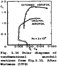 LIVE GRAPH
Click here to view
are referred to the respective chords of either the original or the extended aerofoil). To accomplish such results, the front part of the aerofoil surface must be smooth and uninterrupted, i. e. conventional devices such as slats or Fowler flaps, even in their parked positions, cannot be tolerated. The particular design in Fig. 5.15 also incorporates a small hinged flap at the trailing edge. This is a convenient means for shifting the C^-range of the low – drag bucket and for reducing the pitching moment at high speeds. It may also be used as an aileron.
A new mechanism to vary the eccrriber of a wing has been proposed by J J Spillman
(1973) . This has not yet been tested.


