Applications
2.2 Wing Shape Design
To accurately compare the aerodynamic coefficients (e. g. drag) between small changes of the aerodynamic shape of a wing, it is necessary to be as independent from the CFD mesh as possible. Otherwise, difficulties arise to distinguish between grid discretization effects ("numerical noise" due to change of grid topology) and geometric effects. Nowadays in industrial context a 3D unstructured CFD mesh is not made in a way to obtain a mesh independent CFD solution.
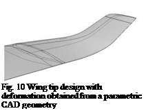
However, mesh deformation conserves the grid topology and small geometry variations produce small mesh deformations in a continuous way. Utilizing this, comparisons of aerodynamic coefficients are better possible and thus uncertainties otherwise introduced by changes of grid topology are minimized. Mesh deformation with FSDeformation was here successfully applied to a shape design change for a wing-tip (figure 9).
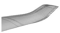
The discrete deformation field was obtained from the parametric CAD model (CATIA V5) using a two-stage process (first the treatment of curves and then surfaces). In a predictor step, the deformation field is determined by subtracting points on discretized corresponding CAD curves. This gives an initial surface deformation which may not be accurate on the inner region of surface panels apart from the bounding curves.
|
Fig. 9 Wing tip shape design example |
 |
 |
(a) Parametric CAD geometry (b) Discrete deformation field calculated
from parametric CAD
In the corrector step surface points are projected to the new CAD geometry. The projection vectors together with the displacement vectors of the discretized curves then builds the final discrete deformation field (figure 10(b)). It serves as input for the new tool FSDeformation to accurately move all points of the CFD grid corresponding to the parametric change of the CAD geometry.


