FAR FIELD CALCULATION OF INDUCED DRAG
It is possible to compute the forces acting on a body or wing by applying the integral form of the momentum equation (Eq. (1.19)). For example, the wing shown in Fig. 8.29 is surrounded by a large control volume, and for an inviscid, steady-state flow without body forces, Eq. (1.19) reduces to
f P4(4 * n) dS = F — f pndS (8.143)
Js Js
where the second term in the right-hand side is the integral of the pressures. A
|
FIGURE 8.29 Far-field control volume used for momentum balance. |
coordinate system is selected such that the x axis is parallel to the free-streanj, velocity t/„ and the velocity vector, including the perturbation (и, v, и») becomes
q = (U«, + u, v, w) ]
If the x component of the force (drag) is to be computed then Eq. (8.143) becomes
D = — I p(U„ + «)[(!/« + u)dy dz + v dxdz 4- wdx dy — f pdydz The pressures are found by using Bernoulli’s equation:
p ~p«, = ^ Ul – ^ [(£/00 + и)2 + v2 + w2] = – puU„ ~^(u2 + v2 + w2) Substituting this result into the drag integral yields
D = — p I + u)dy dz — pf (U„ + u)(u dy dz + vdxdz + wdxdy)
+ pf uU„dy dz +^- f (и2 + v2 + w2) dy dz (8.144)
h 2 Js
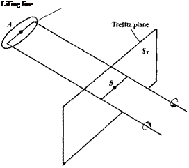
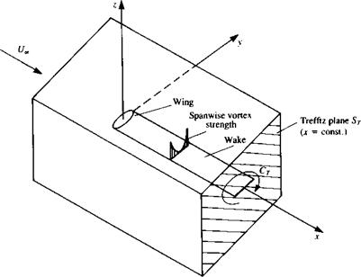
Note that the second integral will vanish due to the continuity equation for the perturbation, and the first and the third will cancel out. Now if the control volume is large then the perturbation velocity components will vanish everywhere but on the wake. If the flow is inviscid, then at this plane ST shown in Fig. 8.30 (called the Trefftz plane) the wake is parallel to the local free stream and will result in velocity components only in the у and z directions (thus u2«v2, w2). Therefore, the drag can be obtained by integrating the v
 FIGURE 8.30
Trefftz plane used for the calculation of induced drag.
and w components on this plane only:
where Ф is the perturbation velocity potential. Use of the divergence theorem to transfer the surface integral into a line integral (similar to Eq. (1.20)) results
The third term in the first integral is canceled since in the two-dimensional Trefftz plane У2Ф = 0 and the integration is now limited to a path surrounding the wake (where a potential jump exists). If the wake is modeled by a vortex (or doublet) distribution parallel to the x axis, as in Fig. 8.30, the formulation of Section 3.14 for continuous singularity distributions can be used. Because of the symmetry of the induced velocity above and under the vortex sheet this integral can be reduced to a single spanwise line integral:
 о fbwf2 p [bw/z
D = “ ДФи»гіу = — T(y)wdy 2 J-bj2 2 J~bwn
the minus sign is a result of the ЭФ/Эп direction pointing inside the circle of integration and bw is the local wake span. In Eq. (8.146) a “horse shoe” vortex structure is assumed for the lifting wing, but the wake span is allowed to be different from the wing’s span (e. g., due to self-induced wake displacement).
Following the same methodology, the lift force can be derived as
L = pU„ f^ ДФ dy = pU„[" Г(у) dy (8.147)
J-bJ2 J-bJ2
The above drag formula may be useful in measuring the accuracy of data that is obtained by numerical integration of the local pressures. As an example for the use of Eq. (8.146), consider the elliptic lifting-line model of Section 8.1. The downwash at the lifting line (point A in Fig. 8.30) due to the elliptic load distribution is constant (Eq. (8.24)):
This was a result observed on the lifting line due to the semi-infinite trailing vortex lines. However, far downstream at a point В (in Fig. 8.30) the downwash is twice as much since to an observer at this point the vortex sheet seems to be infinite in both directions. Using the elliptic distribution Г(у) of Eq. (8.21) and by substituting w, into Eq. (8.146) the drag force becomes
P Cb>2 лЬ я
D = t" 2w, I T(y) dy = pw, — Гтах ~ рГтах 2 J-ы2 4 8
which is exactly the same result as in Eq. (8.27). Also, in this case a rigid wake
model is used and the wake span bw was assumed to be equal to the wing
span b.


