Flow Morphology of Dynamic Stall
The effects of unsteady motion on unsteady airfoil behavior and dynamic flow separation have been recognized for many years, mainly through studies of oscillating airfoils in wind-tunnel experiments. As mentioned previously, for an increasing AoA it has been observed that the flow remains attached to the upper surface of an airfoil to an AoA much higher than that could be attained quasi-statically, giving a corresponding increase in maximum lift. Kramer (1932) was one of the first investigators to observe the phenomenon. The delay in the onset of flow separation under unsteady conditions is a result of three primary unsteady phenomena. First, during the conditions where the AoA is increasing with respect to time, the unsteadiness of the flow resulting from circulation that is shed into the wake at the trailing edge of the airfoil causes a reduction in the lift and adverse pressure gradients compared to the steady case at the same AoA. This “classical” effect has been described in Section 8.6. Second, by virtue of a kinematic induced camber effect, which has also been described in Section’8.6, a positive pitch rate further decreases the leading edge pressure and pressure gradients for a given value of lift. This can be considered a quasi-steady effect. Ericsson (1967), Carta (1971), Johnson & Ham (1972), Ericsson & Redding (1972), McCroskey (1973), and Beddoes (1978) have given a good summary of these basic effects from the perspective of unsteady airfoil theory. Third, in response to the external pressure gradients, there are also additional unsteady effects that occur within the boundary layer, including the existence of flow reversals in the absence of any significant flow separation – see McAlister & Carr (1979). These unsteady boundary layer effects have been quantitatively examined by Scruggs et al. (1974), Telionis (1975), and McCroskey (1975). Although the behavior of unsteady turbulent boundary layers is still not fully understood, the onset of flow separation on airfoils is generally found to be delayed by unsteady effects such as those associated with increasing pitch rate. Coupled with the aforementioned pressure gradient reductions, the resulting lag in the formation of boundary layer separation causes the onset of dynamic stall to be averted to a significantly higher AoA than would be obtained under quasi-steady conditions.
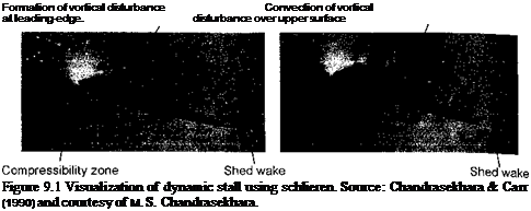
 Ultimately, however, with increasing AoA, the high adverse pressure gradient that builds up near the leading edge under dynamic conditions causes flow separation to occur there. Experimental evidence suggests the formation of a free shear layer that forms just downstream of the leading edge, which quickly rolls up and forms a vortical disturbance. This feature is now known to be a very characteristic aspect of dynamic stall and is shown in the flow visualization images in Fig. 9.1. Not long after it is formed, this vortical disturbance leaves the leading edge region and begins to convect over the upper surface of the airfoil. This induces a pressure wave that sustains lift and produces airloads well in excess of those obtained under steady conditions at the same AoA. A qualitative understanding of this vortex shedding phenomenon was first given by Ham (1968) and McCroskey (1972a, b) and is reviewed by Beddoes (1979). A great number of subsequent experimental studies have provided a much more comprehensive physical understanding of the factors that determine the onset of dynamic stall, including the important influence of compressibility – see Beddoes (1978, 1983), Lorber (1992), and Chandrasekhara & Carr (1990, 1994). However, there have been fewer experimental studies of dynamic stall at the combinations of Reynolds numbers and Mach numbers that would be useful to the helicopter analyst. r ortunately, a few studies have been commissioned to study the effects of compressibility bn the quantitative effects of dynamic stall on airfoils operating at or near to full-scale rotor. Reynolds numbers – see, for example, Liiva et al. (1968) and Wood (1979). Generally, the results have shown that the qualitative features of the dynamic stall process remain similar
![]()
 |
(b)a = 17.1°
over a fairly wide range of Mach numbers and also under different types of forcing condition (i. e., for pitching oscillations, plunging oscillations, and ramp or constant angular rate motions). Yet, the quantitative behavior of the airloads shows subtle variations with Mach number, especially for different airfoil shapes and under 3-D conditions. It is these more subtle aspects of the dynamic stall problem that make its accurate prediction difficult for the helicopter rotor analyst.
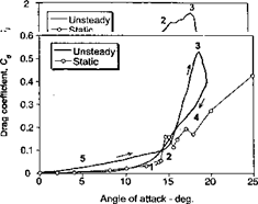
The various stages of the dynamic stall process are summarized schematically by means of Fig. 9.2. Stage 1 represents the delay in the onset of flow separation in response to a reduction in adverse pressure gradients produced by the kinematics of pitch rate (induced camber), the influence of the shed wake and the unsteady boundary layer response. Stage 2 of the dynamic stall process involves flow separation and the formation of a vortex disturbance that is cast-off from the leading edge region of the airfoil. This vortex disturbance provides additional lift on the airfoil so long as it stays over the upper surface. In some cases, primarily at low Mach numbers, the additional “lift overshoots” produced by this process may be between 50 and 100% higher than the static value of maximum lift. The effective lift-curve – slope may also increase during this process. These, often surprisingly large increments in lift, are also accompanied by significant increases in nose-down pitching moment, which results from an aft moving center of pressure as the vortex disturbance is swept downstream across the chord. The speed at which the vortex convects downstream has been documented to be between one third and one half of the free-stream velocity – see Beddoes (1976) and Galbraith et al. (1986). It will also be seen from Fig. 9.2, that the sudden “break” in the lift coefficient at the start of Stage 3 occurs at a higher AoA than that for the divergence in the pitching moment; that is, the pitching moment break (moment stall) occurs at the onset of vortex shedding (start of Stage 2), whereas the lift break (lift stall) occurs when the vortex passes into the wake (end of Stage 2 and start of Stage 3).
After the vortex disturbance passes the trailing edge of the airfoil and becomes entrained into the turbulent wake downstream of the airfoil, the flow on the upper surface progresses to a state of full separation. This is referred to as Stage 4 of the dynamic stall process: it is accompanied by a sudden loss of lift, a peak in the pressure drag and a maximum in nose-down pitching moment. In this flow state, the airloads are approximately the same as those found under steady conditions at the same AoA. Flow reattachment can take place if and when the AoA of the airfoil becomes low enough again. However, there is generally a significant lag in this process [see Green & Galbraith (1995)]. First, there is a
 |
 |
Figure 9.2 Schematic showing the essential flow morphology and the unsteady airloads during the dynamic stall process on an oscillating 2-D airfoil. Adapted from Carr et al. (1977) and McCroskey et al. (1982).
general lag in the reorganization of the flow from the fully separated state until it becomes amenable to reattachment. Second, there is a lag because of the reverse kinematic “induced camber” effect on the leading edge pressure gradient by the negative pitch rate (see also Question 8.2). Therefore, full flow reattachment may not be obtained until the airfoil is well below its normal static stall angle, as denoted by Stage 5 in Fig. 9.2. In this particular case, it is apparent that the AoA falls to as low as 5° before the flow can be considered as fully attached. Because of these lags in the development of the various flow states, a large amount of hysteresis is present in all three components of the unsteady airloads. These hysteresis effects are the source of reduced aerodynamic damping, which as mentioned previously, can potentially lead to aeroelastic problems on the rotor.


