FORCES AND MOMENTS OF STRAIGHT WINGS
Wing moments are usually the consequence of changes in the lift distribution. Rolling and yawing moments are thus coupled with each other and they may be a function of lift, i. e. of the wing’s lift coefficient. (2)
Lift of Sideslipping Wings. According to the cross-flow principle, Chapter XV, the lift of a two-dimensional airfoil kept at a certain angle of attack (measured in the direction of the airfoil chord) varies as
L~cos2/^ (l)
|
Cyf « — sin£* – C/>3 P /180 (3) |
|
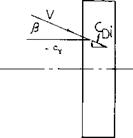
Component of Lift. Assuming that the lift or total- pressure-force vector of a sideslipping wing may still be in a plane normal to the X Y axis, figure 1, the induced drag must be expected to present a lateral component normal to the direction of flow or flight, as indicated in the sketch in figure 4. That component is Cyx=-CD: sin^ dCy^/dfi = – CL[125]1 nr A dCy-c/dyft° =-CL* /180 A (5) |
 |
 |
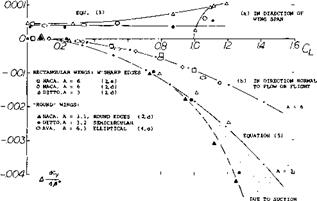
With a section-drag coefficient CDS = 0.02 the average lateral force derivatives of wing models in reference to the stability axis system (in the direction perpendicular to the X axis) is given on figure 3 in comparison with test data. Based on the test data the force seems to increase somewhat with the lift coefficient. Note that in a smooth full-scale wing C03 = 0.01 or less would be closer to reality.
Consequently:
dCyf /dfi°^ – 0.0001 to 0.0002 (4)
which is extremely small in comparison to components due to dihedral, fuselage and vertical tail of an airplane (3).
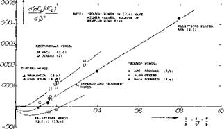
This equation, plotted in the lower part of figure 3, for A = 3 and = 6, is sufficiently well confirmed by experimental results. Note that in the direction transverse to that of flow or flight, the stability axis, both the positive (frictional) and the negative (due-to-lift) lateral forces are existing, while in the airframe system only the frictional component is obtained. Equation (6) was also evaluated as a function of the aspect ratio. Figure 5 suggests that the lateral force due to lift (in the direction transverse to that
|
r _dCY CY»-d^
Figure 3. Lateral force derivative of plane and straight wings as a function of their lift coefficient. |
of flow or flight) may be of appreciable magnitude at higher lift coefficients and/or in smaller A’ratios. “Round” wings (in this case, meaning to have round lateral edges) evidently develop suction forces around the advancing wing tip thus leading to increased negative lateral forces, while sharp-edged rectangular wings (as used frequently in wind-tunnel experimentation) show evidence of a positive lateral component presumably originating at the lateral areas of the wing tips.
|
|
|
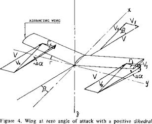
angle Г showing positive change in angle of attack of advancing wing. |
Rolling Moments. Rolling moments are, of course, a consequence of lifting forces; and, within the usual range of the angle of attack where separation does not take place, the rolling moments are found to be proportional to the lift. We can thus conveniently use the derivative dQ/dCL. Early analysis (4,a) predicted, on the basis of lifting-line type of induced angle (downwash) distribution, a “negative” rolling moment derivative, meaning that the wing is expected to roll down into the oncoming wind. This type of moment would not be desirable in the operation of airplanes. Experimental results (for the conventional range of wing aspect ratio), however, do not confirm the prediction. A more advanced theory (4,c) based on lifting surface principles (5) correctly yields “positive” moments due to sideslip, i. e. forces tending to lift up the advancing wing panel.
|
Figure 5. Lateral force derivative of straight wings as a function of their chord/span ratio. |
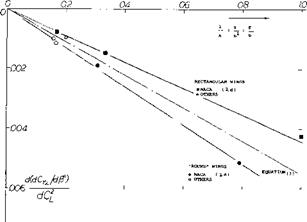
Aspect Ratio. The derivative dC^/dCL is found to be proportional to the angle of yaw, up to plus or minus some 30°, which should cover the full range of sideslipping angles encountered in flight maneuvers. It is, therefore, justifiable to evaluate and to use the derivative
d(dCtld£9)l&CL =dC^./dCi (6)
Experimental results plotted in figure 6 as a function of the wing’s chord/span ratio c/b = 1/A = S/b* agree qualitatively with the complex theoretical functions (not shown in the graph). At very large aspect ratios, below 1/A = 0.1, figure 6, there is evidence of the theoretical result mentioned above whereby the rolling moment to be expected is “negative”. Rectangular wings (as used in wind-tunnel work) have considerably higher positive rolling moments than wings with round tips. Tapered wings (the type most widely used in modern airplanes) have characteristics similar to those of round type wings (where round, this time, is meant to indicate also elliptical or somehow rounded planforms). In conclusion, the rolling moment due to sideslip of straight wings is found to be a function of the aspect ratio and shape of the wing tips or lateral edges.
(4) Analysis of lateral wing characteristics:
(a) Weinig, Sideslipping and Swept Wings, Lufo 1937 p 45.
(b) Hoerner, Characteristics of Wings in Yaw, Lufo 1939 p 178.
(c) Weissinger, Wing in Sideslip, Ybk D Lufo 1940 p 1-138. and 1-145, also 1943 Part IA; see NACA T Memo 1120.
(d) Seiferth, Review, Ringbuch Lu-Technik IA14 (1940).
(5) A finite-aspect-ratio wing at an angle of yaw must be considered as a lifting surface (rather than a “line”). In such a surface the lateral edges tend to become leading and trailing edges, respectively, when increasing the angle of yaw.
|
Figure 6. Derivative of the rolling moment due to sideslip of plan and straight wings. |
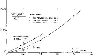
Yawing Moment. The advancing wing panel, producing increased lift, also exhibits increased drag due to lift, which is essentially induced drag; and the drag differential between the two wing panels thus produces a “positive” yawing moment, i. e. a moment tending to return the wing to its original position. For angles of yaw between plus and minus 25 , the wing moment is found to be proportional to that angle. Since induced drag is proportional to the square of the lift coefficient, the yawing moment due to lift is also found to be proportional to that square. We have, therefore, plotted in figure 7 the quantity
d(dC^/d^-)/dC/ = dC^/dQ* (7)
Interpolation of the experimental points does not show any negative moments corresponding to those in figure 6 below 1 /A = 0.1. It is suggested that viscous effects, not taken into account by theory, are responsible for negative values shown.
|
Figure 7. Yawing-moment derivative of plan and straight wings as a function of their chord/span ratio. |


