LATERAL CHARACTERISTICS DUE TO DIHEDRAL
Dihedral of “V” shape has a considerable influence upon forces and moments of sideslipping wings.
Lift Differentials. When placing a dihedraled or “V” shaped wing at an angle of yaw, the angle of attack (against the flow) of the forward panel is geometrically increased; and that of the trailing panel is reduced figure
4. The differential of the angle of attack is
доС = ±АГ (8)
where Г = angle of dihedral. The differential of the lift coefficient in each panel, corresponding to that of the angle of attack, is
A CL =*рГ dCt /doc (9)
When considering a wing with an antisymmetrical variation of the angle of attack, the lift-curve slope to be used in equation (9) corresponds to half the aspect ratio of the wing. Following procedures as given in Chapter III, the “lift angle” to be used in equation (9) is then:
doL° /dCL ~ 10 + (19/0.5 A) (10)
Lateral Force. The lateral force due to dihedral is simply the sum of the spanwise components of the lift differentials in the two wing panels:
Cy<1 =+£Гг dCt /doc (11)
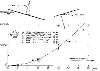
For example, for A = 5 the “lift angle” is do( /dCu = 17 . Measuring all angles in degrees, the lateral force derivative for dihedraled wings with A = 5 is thus expected to be
dCyj. /dp° = + (7Г/180)* Г 2 /17 =
+ 1.8 Г*І�5 (12)
Experimental results for model wings with A = 5 and 6, as plotted in figure 8, confirm the equation.
|
Figure 8. Lateral force derivative of various wings having aspect ratios in the order of 5 and 6, as a function of the dihedral angle. |
Small Aspect Ratios, As shown in Chapter XVII the lift of small aspect ratio wings approximately corresponds to dC^ /dot. = 0.57Ґ A. Using again the half-aspect ratio principle, the lift-curve slope to be used for the differentials in the wing panels is accordingly:
dCJ«± № =0-25^ A (13)
where fi – angle of yaw, in radians. Using this function, and expressing all angles in degrees, equation 11 transforms into
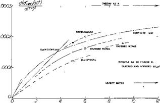
d(dcy/d/j*)/d(r7 =
(ТҐ/180)3 Q. lS’TTk = 0.41 A/IO* (14)
This equation is the straight line as in figure 9. We have also solved and plotted in that graph equation 11 using for the “lift-curve” slope the inverted equation 10, which applies to higher aspect ratios. Experimental results should be bounded by the two theoretical functions. While experimental confirmation is limited to aspect ratios between 5 and 6, the lateral force coefficient due to dihedral must be expected to increase with the aspect ratio.
|
Figure 9. Lateral-force derivative of dihedraled wings as a function of their A’ratio. |
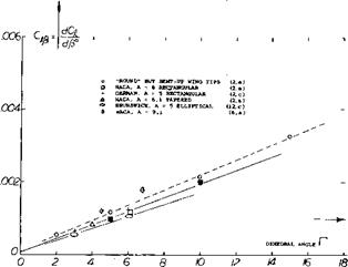
Rolling Moment. Another consequence of the lift differentials as in equation 9 is a rolling moment of the character as plotted in figure 10 for A = 5 and 6. When assuming that the moment arm (b/2) of each wing panel be 0.4, the rolling moment due to dihedral tentatively corresponds to
CJd = 0.5 0А/>Ґ dCL IdoL (15)
Expressing the lift-cuive slope corresponding to equation (10) and measuring all the angles in degrees, we obtain the derivative for the range of higher aspect ratios as plotted in figure 11. For small aspect ratios, we obtain through combination of equations (13) and (14):
d(dC*/d>50)/dr* =
0.5(777180/0.1 “Tr A «5 А/10* (16)
representing in figure 11 the straight line through the origin. As in the lateral force (figure 10) experimental evidence is limited; results are expected to be bounded by the theoretical lines as indicated.
|
Figure 10. Rolling-moment derivative of various wings having aspect ratios in the order of 5 and 6, as a function of the dihedral angle. |
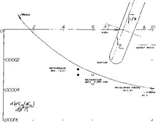
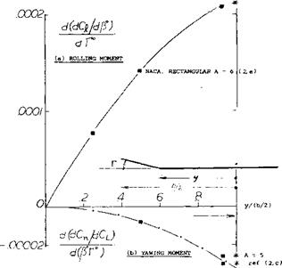
Yawing Moment. When analyzing the moment of a wing with dihedral one could first expect, on the basis of drag, that the advancing wing panel (having higher lift than the trailing panel) must have the higher induced drag, and that a “positive” yawing moment (tending to return the airframe to neutral position) would thus result. Actually, “negative” moment derivatives are found when testing such wings. The lift differentials ACL (as in equation 9) are considerably larger than the induced-drag differentials, and yawing moments corresponding to them are, therefore, predominant. To understand this type of moment,
|
Г*"’ |
|
Numerical Results. The yawing moment of wings with dihedral is plotted in figure 12. Analysis as in (4,c, d) in a simplified form is as follows: The yawing moment due to dihedral of an elliptical wing corresponds to C^ = (2/37Г) CL fir ((A – 1.9)/(A + 3.8)) (17) where the aspect ratio factor is the same as in (4,c, d). For angles in degrees, the derivative is d(dC*/dCt )/d (fr°) = – (6.45/10*) ((A – 1,9)/(A + 3.8)) (18) This function, plotted in figure 12, shows primarily negative yawing moments, increasing in magnitude with the aspect ratio. At aspect ratios below 2, the moment turns positive. Obviously, the induced drag (as in the sketch shown with the graph) grows comparatively large there, so that the lift in the advancing panel is no longer turned forward and that in the trailing panel no longer tilted back in reference to the spanwise direction, as explained in the preceding paragraph. |
|
|||
|
|||
|
|||
|
|||
|
|||
|
|||
|
|||
|
|||
|
|||
|
|||
|
|||
|
|||
|
|
||
|
|||
|
|||
|
|||
|
|||
![]()
![]()
![]()
![]()
Part-Span Dihedral In wing shapes where only part of the span is dihedraled, i. e. where only the wing tips are bent up, moments and forces are, of course, less than those derived above for full-span “V” shape. Figure 13 represents characteristics of a particular wing, having A = 6, as a function of the dihedraled outboard span fraction. It is also possible, however, to design a wing in such a manner that only certain inboard fractions of the two panels are dihedraled; see (6,c). Because of the comparatively short moment arm of the dihedraled portions, the resulting moments are small in this type of wing.
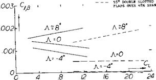
Influence of Wing Flaps. Conventional landing flaps are of the part-span and inboard type. They may also be used (at a moderate angle of deflection) during take-off and while climbing. Their influence upon the characteristics of wings is basically similar to that of tapered plan form and/or wing twist. The variation of Cj^ for flaps deflected (7) indicates a loss of effective dihedral for straight tapered wings, figure 14. The effective dihedral loss appears in this case to be independent of length of the span flaps deflected. [126]
|
aspect ratios in the order of 5 and 6, as a function of their angle of sweep. |
Sweep, primarily meant to indicate swept-back wing shape, causes rolling moments and corresponding yawing moments of an appreciable magnitude.
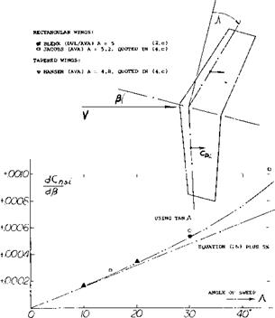
Lift Differential. To understand the character of the rolling moment arising in a swept wing when sideslipping, we will first consider the two panels as though they were separated from each other. Corresponding to the cross – flow principle as discussed in Chapter XV the lift in each panel is then approximately proportional to cos* (A ) where A = angle of sweep as in figure 14. It is explained, however, in (4,c) that in a swept wing (where the two panels are connected with each other) the reduction of lift is only proportional to cos(A+^). The local lift coefficient in each panel is thus:
CLS ” CL cos(A+/3) =
CL (cos.0 cos Л+ sin /3 sin A) (19)
where “s” indicates “sweep” and where CL = original combined lift coefficient of the wing. The differential between the two panels (based on total wing area) is then
Д CL =CL sin^sinA (20)
In a wing of finite aspect ratio, the distribution of the induced angle of attack varies in such a manner that the lift in the advancing panel is somewhat increased above that as in equation (19) while the lift in the trailing panel is somewhat reduced. As a consequence, (4,c) indicates
A CL =CL sin^ (tan A+2 sinA/(A + 4)) (21)
Rolling Moment. The effect of sweep on the rolling moment follows from the last equation by assuming a moment arm for each panel equal to 0.45 b/2; thus CjfS = 0.225 A CL . Measuring p in degrees the derivative is then:
d(dQ/ dy5e)/dCL =
0.225 (tanA+ 2 sinA/(A + 4))тґ/і80
^ .00007° (1 +2/(A + 4)) (22)
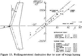
We have plotted this equation in figure 15 for A = 5. While theory leads to an infinite value at A = 90 , because of tan A, tests at higher angles of sweep do not seem to confirm this. Agreement with other experimental points can be improved by shifting the function up by an amount up to 0.001, thus accounting for the moment at zero angle of sweep as in figure 6. Round tip and tapered
![]()
![]()
![]()
![]()
![]()
![]()
![]()
![]() wings may be expected to have lesser moments due to sweep than rectangular (wind-tunnel model) wings. We have labeled the two theoretical lines in figure 15 as ‘‘rectangular” and “round” accordingly. As a function of the aspect ratio, figure 16 presents equation (22) for a moment arm equal to 0.45 b/2. Experimental confirmation is limited to aspect ratios between 5 and 6. The interpretation and extrapolation on the basis of the principles as in (4,c) are considered to be correct, however.
wings may be expected to have lesser moments due to sweep than rectangular (wind-tunnel model) wings. We have labeled the two theoretical lines in figure 15 as ‘‘rectangular” and “round” accordingly. As a function of the aspect ratio, figure 16 presents equation (22) for a moment arm equal to 0.45 b/2. Experimental confirmation is limited to aspect ratios between 5 and 6. The interpretation and extrapolation on the basis of the principles as in (4,c) are considered to be correct, however.
d(dCj/dCL)
d(pr) .00008- .00006 .00004- .00002
ASPECT RATIO
Figure 16. Rolling-moment derivative of swept wings as a function of their aspect ratio.
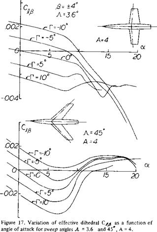
As shown in (8,a) the effective dihedral of swept back wings increases rapidly with CL relative to straight wings, figure 17. At the higher lift coefficients there is a sharp reduction of — Cjifi with an associated drop in the effectiveness of the dihedral angle F. The sharp break in the variation of with lift is caused by the stalling of the tips of the advancing wing, Chapter XVI, which reduces the corrective moment. When operating at low angles the of swept forward wings have little variation with CL. However, as noted in (10) there is a sharp increase of effective dihedral at lift coefficients above .5.
Yawing Moment. For swept wings the differential variation of drag in the two wing panels determines the yawing moment. Considering viscous section drag, the moment arm of this component in each wing panel varies as cos (Л +/£ ). Using the drag coefficient CDS and a moment arm equal to 0.45 b/2, the component of yawing moment caused by viscosity C^sv is then
C77sv = 0.45 CD$ sin^ sin Л (23)
For С^з = 0.01 (as roughly in an airplane wing) we obtain the derivative of the yawing moment due to sweep C ns
dC„5/d X ) = 1.4/10* (24)
which is comparatively small but “positive” .
Component Due to Lift. As a result of the production of lift, and drag due to lift in the wing panels, a “positive” yawing moment is to be expected. Evaluation of analysis in (4,c) yields for an elliptical lift distribution:
dC^/d^ – (CL /5)(dCt/d/5)^ C^tanA/20 (25)
This component is stable, as well as the viscous moment above and varies in proportion to the square of the lift coefficient. Measuring the angles in degrees:
dC^/d/’« 1.5 С/ X�~* (26)
(8) Dihedral effects of swept wings:
(a) Kuhn, Straight and 45 Swept Wings, NACA RML53F09.
(9) Lateral characteristics of swept wings:
(a) Toll, Derivatives of Swept Wing, NACA TN 1581 (1948).
(b) Goodman, A’ratio and Sweep Rolling, NACA TR 968 (1950).
(c) v. Doepp, Ju-287 swept back and forward wing models, Junkers Wind Tunnel Results S-1943, 1 & 2, 46,69,72 and 1944/2.
(d) Hubert, Swept Wings, Yearbk D Lufo 1937 p 1-129.
(e) Luetgebrune, Swept Wings, ZWB Rpt FB-1458 (1941).
(f) Letko, Stability of Swept Wings, NACA TN 1046 (1946). Campbell, Factors Affecting Lateral Stability, NACA Univ Conference 1948.
In a wing of conventional shape, the relative magnitude of the “induced” component and that as derived in this paragraph is such that at small lift coefficients the viscous moment predominates. At lift coefficients in the vicinity of = 1, the induced component is larger than the viscous-type moment for angles of sweep exceeding some 10 , and is very much larger at angles in the order ofЛ = 30°. Since separation of the two components is not readily possible, we have subtracted from tested yawing- moment values the value at or near CL = 0, or sometimes an estimated value (see equation 24); and we have then plotted the remaining values in figure 18. The results are higher than indicated by equation (26). As shown in (4,c) there is a small influence of the aspect ratio in the order of 5% (good for A between 4 and 20). Using also the tangent instead of the angle of sweep sufficient agreement can be obtained. As usual, the rectangular wings have larger moments than tapered ones.
|
Figure 18. Derivative of the yawing moment due to lift as a function of the angle of sweep. |
|
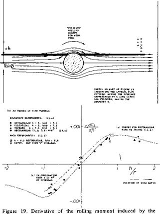
fuselage, as a function of vertical wing position. |
Flow Pattern. Figure 19 presents the basic flow pattern across a fuselage body operating at an angle of yaw. When adding a straight wing in a position which is high in relation to the fuselage, the aerodynamic or effective angle of attack is obviously increased on the windward side and it is reduced on the leeward side. This results in a “positive” rolling moment tending to raise the leading wing panel. This moment is of the same character as that caused by dihedral. Of course, in the case of a low-wing combination, the direction of the resulting rolling moment is opposite to that of the high wing as shown in the illustration. Therefore, presence of the fuselage is the equivalent of a certain amount of
![]()
a) positive wing dihedral for the high-wing


