Lifting-Line Analysis
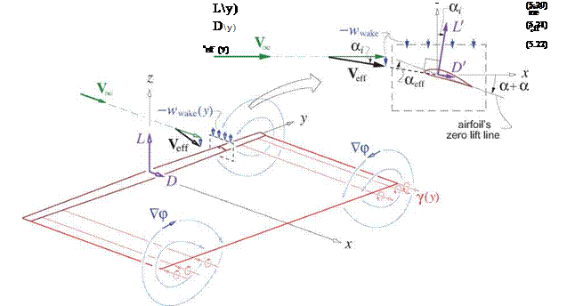
A practical approach to lift and drag calculation for high aspect ratio 3D wings is based on the lifting line approximation. This is actually a hybrid far-field/near-field model which uses the idealized straight-wake approximation together with specified spanwise wing chord and twist distributions c(y) and aaero(y). The lifting-line model hinges on the following assumptions, illustrated in Figure 5.6.
• The near-field flow is 2D, but with an effective freestream velocity Veff. This is the freestream plus the velocity of wake, so that it contains all contributions except those of the vortices and sources representing the local 2D wing section. These are intentionally not shown in Figure 5.6, since they do not contribute to Veff. The wake vorticity lies mostly along the freestream, so its downwash velocity wwake at the wing is in the vertical z direction, and therefore acts primarily to tilt the freestream by
|
the induced angle a. |
|||
|
Veff — К» x + wwakez |
(5.17) |
||
|
— wwake |
|||
|
сїі = arctan ——— ~ |
Ко |
(5.18) |
For a positive (upward) lift, the downwash is typically negative and hence a is positive.
• At each spanwise location, wwake is assumed to be nearly uniform over the chordwise extent of the wing’s airfoil, so that a acts to modify the airfoil’s angle of attack at that location.
• At each spanwise location y, wwake(y) is related to the wake vortex sheet strength 7 at all spanwise locations y’ by considering the wake to be a row of semi-infinite vortex filaments of strength j(y’) dy’. The vertical velocity at у, of a filament at y’, is then dwwake = 7 dy’/4n(y—y’). Integrating this over the span y = — b/2 … b/2 gives the overall local downwash.
dp 1 fb/2 Y(y’)
-^(0,y,0) = Wwake(y) = — – jdy’ (5.19)
dz 4n – b/2 y—y’
The physical lifting-line model described here does not require that the wing be unswept. However, classical wing analysis methods based on the lifting-line model, like the one given in Appendix E, do assume zero sweep. For simplicity, the rest of this section will also assume zero sweep.
|
2^V^co £ Cd,{c*eff) a + aaero ai |
 |
A very attractive feature of the lifting-line approximation is its ability to exploit known airfoil characteristics. Because the near-field flow is effectively 2D, its lift/span and drag/span are described by the usual 2D airfoil coefficients в£, Cd corresponding to the wing-section airfoil shape at that location.
 |
 |
|
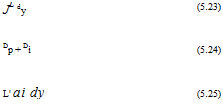
Here aeff is the effective local angle of attack, which is less than the overall aerodynamic angle a+aaero(y) because of the induced angle ai(y). The induced angle also rotates the local lift and drag forces L’, D’ as indicated in Figure 5.6. Projecting L’, D’ onto the global freestream-aligned z, x axes and integrating over the span gives the overall lift and drag L, D.
The rightmost (approximate) forms of the L, D expressions assume
ai 1 , cd c£
which is valid for high aspect ratio wings with unstalled airfoils.
Although the above lifting-line analysis has defined the overall wing lift and the wing drag components in terms of the relevant quantities, it is not fully predictive as given. Actual calculation of the forces would require knowledge of the vortex sheet strength distribution y(y) as a starting point. This is determined from the wing geometry using the classical procedures given in Appendix E.
The lifting-line force analysis summarized by equations (5.23) and (5.24) is seen to naturally produce a breakdown of the total drag D into profile drag and induced drag components Dp and Di, and gives them in terms of the sectional D’, L’ forces and the induced angle ai by relations (5.25). The main limitation of this analysis is that it assumes a high aspect ratio wing. For low aspect ratio wings, or more general lifting body shapes like the one shown in Figure 5.4, the vertical velocity wwake of the vortex wake cannot be assumed to be uniform across the chord. In this case a locally-constant induced angle ai and hence a local effective angle of attack aeff(y) cannot be defined, so that the lift and drag coefficient cg and Cd in (5.20) and (5.21) cannot be uniquely determined. Furthermore, with low aspect ratios the locally-2D flow assumption becomes invalid, so that the 2D coefficients cg and Cd would become questionable even if some suitable chord-averaged aeff could be assumed. The overall consequence is that lift and drag expressions (5.23), (5.24) become inapplicable for general body geometries. These limitations will be avoided with the more general far-field force analyses considered in the subsequent sections.


