Polhamus Method
The Polhamus method assumes that the lift on a delta wing consists of two parts: potential flow lift and vortex lift. The potential flow lift is calculated by assuming that there is no leading-edge suction developed at the leading edge of the delta wing because the streamlines pass smoothly around the leading-edge separation bubble, as shown in Fig. 6.30c. It is further assumed that the flow reattaches on the upper surface of the wing after passing around the separation vortex. Thus, the flow model assumes that the potential flow lift is decreased only by the loss of the leading-edge suction force. Lifting-surface theory may be used to calculate the potential flow lift.
As noted previously, the vortex-lift method of Polhamus does not attempt to model flow details. Rather, it recognizes that there must be a force on the wing arising from the pressure required to keep the centrifugal force in equilibrium as the flow passes around the separation vortex. It is assumed that this force is of the same magnitude as the leading-edge-suction force required to sustain attached flow around a large leading-edge radius (see Fig. 6.30b). The difference is that the force due to separation acts primarily on the upper surface (see Fig. 6.30c) rather than on the wing leading edge (see Fig 6.30b). In effect, the leading-edge-suction force is assumed to rotate 90° and become perpendicular to the wing-chord plane. The result is that there is a normal force exerted on the wing (force F in Fig. 6.30c) that adds to wing lift.
According to the Polhamus model, the lift on a delta wing becomes:
CL = (potential flow lift) + (vortex lift)
or
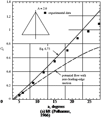
CL = KP sin a cos2 a + Kv cos a sin2 a (6.73)
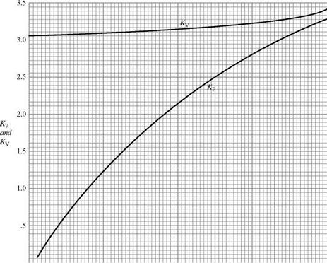
where KP and Kv are constants that can be found from lifting-surface theory and a is the angle of attack of the delta wing. The constants for a delta wing in incompressible flow are shown in Fig. 6.31 as a function of the AR of a delta wing at a very low speed.
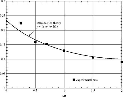
The loss of leading-edge-suction force due to the presence of the separation vortex results in a drag penalty. The same simple approach also can be used to predict the inviscid drag due to lift of a sharp-edged delta wing at low speeds with vortex lift and zero leading-edge suction (Polhamus, 1968). Namely:
|
0 0 .5 1.0 1.5 2.0 2.5 3.0 3.5 4.0 Figure 6.31. Values of KP and Kv for a delta wing at M = 0 (Polhamus, 1968). |
where DLift is the drag due to lift (not written as because it is not associated with a trailing-vortex sheet).
This theory (i. e., Polhamus) predicts results with excellent agreement with experimental data up to large angles of attack (Fig. 6.32). The theory describes the behavior of a delta wing to very large angles of attack. Ultimately, at an angle of attack that depends on the AR of the delta wing; the theory begins to over-predict the lift on the wing as the measured lift begins to drop off. At this angle of attack, the spiral vortex has started to break down (i. e., the vortex begins to experience what is called vortex burst). The vortex breakdown proceeds from the trailing edge of the wing to the front. At some point, the vortex completely breaks down, the upper surface of the wing is a turbulent separated region, and the delta wing experiences stall.
The leading-edge-suction analogy described previously was extended to predict the behavior of arrow – and diamond-wing planforms. Charts for evaluating KP and Kv needed to calculate the potential flow and vortex-lift terms for these planforms are in work by Polhamus, 1971. A subsonic-compressibility procedure is included as well.
The previous discussion applied only to steady flight. Vortex lift also is important in fighter operations at high subsonic speed when a high value of lift is desired for maneuvering and control, which corresponds to a time-dependent problem. During maneuvers, the spiral vortex from the leading edge changes strength with time and the location of the vortex-bursting is time-dependent. The unsteady vortex – lift problem is discussed in Nelson, 1991.
 |
|
|
|


