Semi-Empirical Models of Dynamic Stall
Some typical engineering or semi-empirical models that have been used (or are currently being used) for modeling dynamic stall and that may be suitable for rotor airloads
predictions and rotor design analyses are as follows:
1. UTRC a, A, В Method: This is a resynthesis method, with the approach being described by Carta et al. (1970) and Bielawa (1975). The basis of this method is that in attached flow the airloads can be expressed in terms of the forcing parameters a, A — ac/2V, and В = otc2/AV2. In an attempt to isolate the dynamic contributions to the airloads, the static coefficients are subtracted from the total airloads. By appropriate crossplotting and interpolating for given instantaneous values of these parameters, the contributions to the dynamic airloads can be reconstructed and added to the static values. The method has met with some success, but large data tables must be generated for each airfoil and for each Mach number. A further development of this model that obviates the need for large tables is given by Bielawa (1975).
2. Boeing-Vertol “Gamma” Function Method: This model was initially developed by Gross & Harris (1969) and Gormont (1973). In the “gamma” function method, the influence of airfoil motion is determined by computing an effective AoA. First, the influence of plunging and pitching effects in attached flow is obtained by applying a “correction” to the AoA derived from Theodorsen’s theory at the appropriate reduced frequency of the forcing. From this, a second correction is applied from the instantaneous value of the “gamma” function. This gamma function is obtained empirically as a function of Mach number from 2-D oscillating airfoil tests on the appropriate airfoil. The corrected AoA is then used to obtain values of the airloads from the static force and pitching moment curves. This has the effect of delaying the onset of stall to a higher AoA with increasing pitch rate, a result observed experimentally. The pitching moment is obtained from an empirically determined center of pressure function. Good predictions of the unsteady airloads are possible with this method [see Harris et al. (1970)], but the quantitative accuracy even for 2-D airfoils is deficient for conditions of stall onset or light dynamic stall. This model has been used in a comprehensive rotor analysis for the prediction of helicopter rotor airloads – see Gormont (1973).
3. Time-Delay Method: Beddoes (1976,1978) has developed a semi-empirical model for dynamic stall. Unlike the previously described resynthesis methods, the philosophy behind this method is to try to model, albeit still in a very simplified manner, the basic physics of the dynamic stall process itself. The method is based in the time domain. The behavior of the airloads in attached flow is obtained from Duhamel superposition using the Wagner indicial response function. Corrections are applied to this function to account for the effects of compressibility. Although scaling the Wagner function in this way is not rigorous, the results obtained approximately replicate the increased lag in the unsteady loads resulting from compressibility effects. The key feature of this model is the use of two nondimensional time delays (based on semi-chords of airfoil travel). These time delays represent periods of nondimensional time that exist between identifiable dynamic stall flow states. The first time delay represents the delay in the onset of flow separation after the static stall angle has been exceeded and the time required for the initial separation to develop. The second time delay represents the time during which the leading edge vortex shedding process occurs. These time delays have been obtained from an analysis of many airfoil tests over a relatively wide range of Mach number. Similar studies have been done by Galbraith et al. (1986) but at lower Mach numbers. The results from the time-delay model have been shown to give good predictions of the unsteady airloads on 2-D airfoils. The method also requires relatively few empirical constants.
4. Gangwani’s Method: Gangwani (1982, 1984) has developed a synthesized airfoil method for the prediction of dynamic stall. This method is also based in the time domain. To model the airloads in attached flow, a “Mach-scaled” Wagner function with a finite-difference approximation to the Duhamel superposition integral is used, very much in the same manner as for the Beddoes time delay model. In the nonlinear part of the model, a series of equations with several empirical coefficients are used to represent the forces and pitching moments produced by the various dynamic stall events. These equations are based on the determination of “delayed” series of AoA, with the associated coefficients being derived from steady and unsteady airfoil data. Although a disadvantage with the method is the relatively large number of equations and empirical coefficients, nearly all of which are derived from oscillating airfoil data, credible predictions of the unsteady airloads have been demonstrated. The capabilities of this model have been independently evaluated by Reddy & Kaza (1987). One of the main difficulties with this method seems to be in predicting flow reattachment after dynamic stall.
5. Johnson’s Method: Johnson (1969, 1974) has developed a relatively parsimonious representation for incorporating dynamic stall effects on the sectional airloads. The experimental data of Ham & Garelick (1968) were used to develop the model in a form that could be used to correct the static stall lift and pitching moments as functions of pitch rate. Stall onset was represented by defining vortex shedding to occur just above the static stall AoA. It was assumed that vortex shedding produced increments in lift and nose-down moment that increased linearly to a peak value over a finite time, followed by a decay back to the static loads. Reasonable predictions of the unsteady lift seem possible with this method, although the pitching moment predictions appear less pleasing.
6. Leishman-Beddoes’s Method: Leishman & Beddoes (1986,1989) have developed a model capable of representing the unsteady lift, pitching moment and drag characteristics of an airfoil undergoing dynamic stall. The model has been developed to overcome certain shortcomings of other unsteady aerodynamic models that were available up to about 1980 for use in rotor design and aeroelasticity analysis. The emphasis in this model is on a more complete physical representation of the overall unsteady aerodynamic problem, while still keeping the complexity of the analysis down to minimize computational overheads. The model was initially developed by Beddoes (1983) and Leishman & Beddoes (1986, 1989), with various refinements by Leishman (1989) and Tyler & Leishman (1992). Extensive validation of the model has been conducted with experimental measurements.
This model consists of three distinct subsystems arranged in the form of a Kelvin chain as shown in Fig. 9.7: 1. An attached flow model for the unsteady (linear) airloads, 2. A separated flow model for the nonlinear airloads, and 3. A dynamic stall model for the leading edge vortex induced airloads. An important feature is that more rigorous representations of compressibility effects are included in the attached flow part of the model. These are represented using the indicial response functions for compressible flow (Section 8.15), along with linear superposition in the form of more accurate finite-difference approximations to the Duhamel’s integral. The treatment of nonlinear aerodynamic effects associated with separated flows are derived from Kirchhoff-Helmholtz theory, which can be used to relate
Output of unsteady airloads
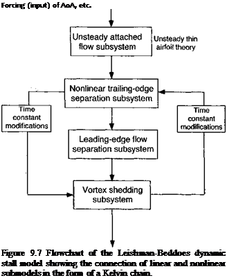 |
the airfoil lift to the AoA and the trailing edge separation point, a technique discussed previously in Section 7.11.5 .In application, the experimental static lift stall characteristics are used with the Kirchhoff-Helmholtz model to define an effective separation point variation that can then be generalized empirically and used to reconstruct the nonlinear airloads for any AoA. To represent the effects of dynamic stall, a third subsystem contains equations that emulates the dynamic effects of the accretion of vorticity into a concentrated leading edge vortex, the passage of this vortex across the upper surface of the airfoil, and its eventual convection downstream. The dynamic stall process begins when an equivalent leading edge pressure parameter reaches a Mach number dependent critical value indicative of leading edge or shock induced separation. To simulate the effects of the complex viscous dominated flow morphology during dynamic stall, the various time constants that describe the behavior of this third subsystem, and also of the trailing edge separation point subsystem, are modified in a logically determined sequence. One significant advantage of this method is that it uses relatively few empirical coefficients, with all but four at each Mach number being derived from static airfoil data. This model has also been adapted and modified by Pierce & Hansen (1995) for the class of airfoil sections used on wind turbines (see Section 13.9).
ONERA Method: This model describes the unsteady airfoil behavior in both attached flow and during dynamic stall using a set of nonlinear differential equations. The model was first described by Tran & Pitot (1981), Tran & Falchero (1981),
and McAlister et al. (1984), with various modifications by Peters (1985). A version of the ONERA model has been evaluated by Reddy & Kaza (1987). A later version of the model (the ONERA Edlin model) is documented by Pitot (1989). The coefficients in the equations of this model are determined by parameter identification from experimental measurements on oscillating airfoils. Like several other models, including the Leishman-Beddoes model, the airloads are expressed as a sum of two components: a component associated with the linear (attached flow) behavior and an increment that represents a deviation from the linear value resulting from stall. The model requires 22 empirical coefficients for each Mach number. The later ONERA BH model, as documented by Truong (1993, 1996), requires 18 coefficients and also adapts the Kirchhoff-Helmholtz trailing edge flow separation scheme from the Leishman-Beddoes model.
Generally, reasonable predictions of the unsteady airloads are obtained with the ONERA model – see also Tan & Carr (1996) and Nguyen &~ Johnson (1998). However, like many of the models, the predictions are deficient for flow reattachment after dynamic stall. Based on the experimental studies of Green & Galbraith
(1995) , the modeling of dynamic flow reattachment requires as much care as for modeling dynamic flow separation, especially if accurate predictions of aerodynamic torsional damping are an objective. A apparent advantage of the ONERA method is that because all of the equations for the lift, drag, and pitching moment are written as differential equations, they are in a form that can be immediately useful for various types of aeroelastic analysis. However, the Leishman-Beddoes model has also been cast into differential equation form – see Leishman & Crouse (1989) and Leishman & Nguyen (1990). Furthermore, it would seem that the structure of some of the other semi-empirical dynamic stall models may also lend themselves to be cast into the same mathematical form, if required by the analyst.
8. Neural Network Methods: Recursive neural network (RNN) models are a class of nonlinear mathematical methods that have been used to model the effects of dynamic stall – see Faller & Schreck (1996). These models are developed in state – space form, where the state-matrix is developed recursively by “training” neural estimators. Like all semi-empirical models the method first requires access to a data set of measurements that can be used to train the model. In this postdiction (or calibration) phase the simulation error is progressively reduced to reproduce accurately the known input data. An assumption must be made as to the elements of the input forcing; generally the approach has met with reasonable success in reproducing the unsteady airloads under the assumption of simple inputs, such as a, a, and a. In some respects this approach is similar to the character of the UTRC model. However, for a helicopter rotor other elements of forcing are clearly involved (see Fig. 8.2) and training the model for more complicated interdependent inputs still requires further development. In some cases training data for certain modes of forcing may not be available, making RNN models less certain in terms of their ultimate predictive capability. Furthermore, RNN methods have not yet shown convincing results when reduced to simulate the “classical” problems m unsteady aerodynamics, such as idealized harmonic oscillations, nonuniform free – streams or vertical velocity fields, and indicial type problems. The large number of states also makes the RNN approach less attractive for many types of helicopter rotor applications, although the rapid advances in computer speeds makes this less of an issue than it might have been ten or more years ago.
9.5.2 Capabilities of Dynamic Stall Modeling
Based on the foregoing discussion, there are several different dynamic stall models available to the helicopter rotor analyst, all of which represent, to an engineering level of approximation, the forces and pitching moments produced on an airfoil during dynamic stall. Reddy & Kaza (1987) have compared and contrasted several of these models, from which the general quantitative capabilities and deficiencies were independently documented. Used intelligently, it would seem that most of these models are adequate for use in a wide variety of rotor analyses. Much comes down to the confidence levels that
____ лп4-лиі:«ил4 4-і____________________________ u л_________ u~<-u л о гл „,лп
СШі ис cbuauiiMicu uuuugii іллісшішіі &шши, ииш аі а icvci аь wcu аа inaiuc uic rotor environment. Tan & Carr (1996) have presented a summary of results for a number of currently used semi-empirical dynamic stall models, as well as first-principles based CFD approaches to the dynamic stall problem. Results have been compared for both an oscillating 2-D-airfoil and an idealized 3-D problem in the form of an oscillating cantilevered finite-wing (see Section 9.9). Again, it seems that if the semi-empirical models are used intelligently, very credible predictions of the integrated airloads can be obtained when compared to experimental measurements.
In the following discussion, predictions made by the Leishman-Beddoes model [see Leishman & Beddoes (1986, 1989)] will be used to show the general capabilities of the semi-empirical dynamic stall models. While it should be appreciated that some models might produce different or better results, the idea here is simply to illustrate the overall levels of performance that could be expected from these types of engineering models. It is obviously highly desirable to expose the models to different types of forcing, that is, not solely for oscillatory pitching as might have been used for formulation purposes. As mentioned previously, a large proportion of the aerodynamic changes m AoA that take place in the rotor environment come from blade flapping, which is equivalent to a plunging or heaving type of forcing at the blade element level. One underlying assumption that seems to be made in nearly all the various unsteady aerodynamic models described above is that the effects of blade motions and wake inflow variations can be adequately represented by a lumped “equivalent” AoA – see Eq. 8.182. This proves an adequate assumption for fully attached flows, but Fukushima & Dadone (1977) and Ericsson & Reding (1983) have argued that more fundamental differences may exist in the dynamic stall airloads when different modes of motion are imposed (i. e., pitching versus plunging). This perhaps raises some questions about the capabilities of the various dynamic stall methods, in general, to predict accurately the unsteady airloads for completely arbitrary variations in AoA, pitch rate, and so on. However, while many 2-D oscillating airfoil experiments have been conducted to study dynamic stall, only a few experimental facilities can simulate both pitching and plunging oscillations or other combined motions so that this can be thoroughly verified. This is mainly because plunge experiments are mechanically difficult to perform in a wind tunnel environment, especially over the wide rsnge of amplitudes und reduced frequencies that would be necessary to validate any theory. I. iiva et al. (1968) and Carta (1979) have measured oscillatory airloads under oscillatory pitch and plunging conditions. However, only the results obtained by Liiva et al. (1968) are for the ranges of Reynolds numbers and Mach numbers that are representative of those found on a helicopter rotor.
Figure 9.8 shows the normal force and pitching moment coefficient responses obtained for oscillatory pitching and plunging into dynamic stall. Notice that the general features of dynamic stall are evident here, with both sets of results showing a qualitative similarity for both types of forcing. The hysteresis loops predicted by the dynamic stall model are in good
|
|
|
|
|
|
|
|
|
|
|
|
|
|
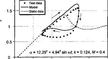
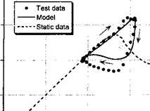
agreement with the experimental measurements – the only significant discrepancy is during the flow reattachment process. In both cases, stall onset is clearly postponed well above the static stall AoA, followed by leading edge vortex shedding. Both conditions suggest that an organized dynamic stall vortex is formed and convected downstream over the chord, although for the plunge case, the degree of stall penetration is slightly less.
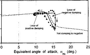
Figure 9.9 shows dynamic stall loops for pitching and plunging oscillations performed at a higher mean AoA. These particular results are for conditions such that the minimum AoA is sufficiently high that the flow can only reattach to the airfoil surface during the latter part of the down stroke in AoA. The agreement of the model with the experimental data is apain ve. rv pond for both nitr. h and піцпрр oscillations The nitchins moment response shows that stall onset is predicted a little early for pitch and later for plunge; in a practical sense these differences are small, however. The maximum nose-down pitching moment for the pitching airfoil is over-predicted, but it is predicted better for the plunging airfoil.
Carta (1979) has concluded that dynamic stall occurred on the airfoils during certain pitch oscillation cases but not in the corresponding plunge cases, even though the same equivalent AoA history was imposed. It appears that this behavior can, in part, be traced to the (inviscid) pressure distribution at the leading edge of the airfoil. For pitch oscillations the favorable “induced camber” effect discussed previously means that, in principle, the leading edge pressure conditions that delimit attached flow should be met at a lower equivalent AoA than for the plunge oscillations. Tyler & Leishman (1992) have confirmed that the stall onset behavior is related to the additional effect of pitch rate contribution to the unsteady airloads during pitch oscillations. Therefore, for “equivalent” conditions the degree of stall penetration and lift and pitching moment hysteresis should be somewhat greater for an equivalent pitch oscillation, confirming Carta’s observation.
Ericsson & Reding (1983, 1984) have put forward an alternative theory, postulating that the differences in the airloads seen between dynamic stall in oscillatory pitching and plunging is a result of two viscous phenomena: the “spilled” leading edge vortex but also another effect called the leading edge jet effect. While the leading edge vortex shedding phenomenon has been well documented experimentally, the role of the leading edge jet effect in the dynamic stall problem is much less clear. Ericsson & Reding suggested that this leading edge jet effect helps to delay the onset of leading edge separation on a pitching airfoil by producing a fuller boundary layer profile. The final result is, however, opposite to that inferred from both Liiva’s data and Carta’s data where, for nominally “equivalent” pitch/plunge forcing, a pitching airfoil is generally found to stall at a lower equivalent AoA.


