Symmetrical double wedge aerofoil in supersonic flow
Example 6.10 Plot the pressure distribution over the symmetrical double-wedge, 10 per cent thick supersonic aerofoil shown in Fig. 6.44 when the Mach 2.2 flow meets the upper surface (a) tangentially; and (b) and (c) at incidence 2° above and below this. Estimate also the lift, drag, and pitching moment coefficients for these incidences.
The semi-wedge angle e0 = arc tan 0.1 = 5.72° = 0.1 radians
M = 2.2; M2 = 4.84; Vm2 – 1 = 1.96
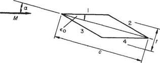 |
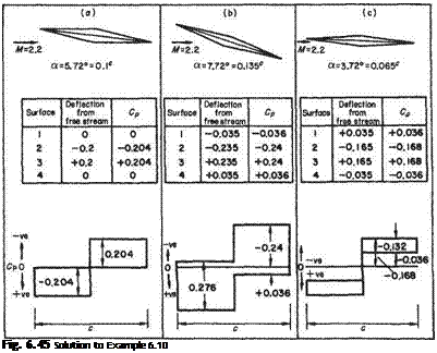
and for the incidence а = єо = 0.1°. Using Eqn (6.146), the distribution is completed in tabular and graphical forms in Fig. 6.45.
 |
For the lift drag and moment a more general approach can be adopted. If a chordwise element 6x, x from the leading edge be taken, the net force normal to the chord is
(Pl ~Pu)6x = (CpL – CpV)^pV26x
Total normal force = lift (since a is small)
L = CLl-pV2c = jcpL – Cpv)PV4x (6.148)
In this case Eqn (6.148) integrates to give
Clc 2 (Сй — Сй) + 2 —
and on substituting CP2 = 2e[VM2 — 1, etc.,
Cl = ~7m2 ^£з-£1+£4-£21 (6.149)
But for the present configuration
£l = £o — Є2 — —£o — &■> 63 = £o + £4 = —£0 + &
when Eqn (6.149) becomes
CL = ^ [(є0 + a) – (є0 – a) + (-є0 + a) + (єо – a)]
In the present example
Силі = 0.132, Cl5.72 = 0.204, Cum = 0-275
The contribution to drag due to a chordwise element of lower surface, say, is
1 .
Pl£lSx = Cpl – pV2£L^x + po£LSx
where po is the free-stream static pressure which integrates to zero and may be neglected throughout. Again using Cpl = lEypjM2 — 1, the elemental contribution to drag becomes
![]() 2ej 1
2ej 1
VM2 – l2f
The corresponding contribution from the upper surface is
 ^-~pV4x
 |
|
The total wave drag becomes
It is now seen that aerofoil thickness contributes to the wave drag, which is a minimum for a wing of zero thickness, i. e. a flat plate. Alternatively, for other than the flat plate, minimum wave drag occurs at zero incidence. This is generally true for symmetrical sections although the magnitude of the minimum wave drag varies. In the present example the required values are
Сд,72 = 0.029, CDil2 = 0.0408, CDlll = 0.0573 Lift to wave drag ratio. Directly from Eqns (6.150), and (6.151):
Now LjD is a maximum when DjL = a 4- {tjc)2 fa is a minimum and this occurs when the two terms involved are numerically equal, i. e. in this case, when a = tjc. Substituting back gives the maximum LjD ratio as
t/c
>(-Г2©
For the present example, with tjc = 0.1, [Z,/D]max = 5 occurring at 5.72° of incidence, and
 = 4.8
= 4.8
M 7.72
Moment about the leading edge Directly from the lift case above, the force normal to the chord from an element Sx of chord x from the leading edge is (CPL — Cpu)^pV2Sx and this produces the negative increment of pitching moment
AM=-(CPL-CPu)x^pV26x
Integrating gives the total moment
-M = J‘(CPL – CPl])^pV2xdx = – CMl-pV4
Making the appropriate substitution for Cp:
which for the profile of the present example gives
-Cm = ^2 I Iа _ єо – (єо – x)] — + [(eo + a) + (a 4- e0)] j
![]() ‘ VM2-!
‘ VM2-!
 |
|
i. e.
and this is independent of Mach number and (for symmetrical sections) of incidence.
Symmetrical biconvex circular arc aerofoil in supersonic flow
While still dealing with symmetrical sections it is of use to consider another class of profile, i. e. one made up of biconvex circular arcs. Much early experimental work
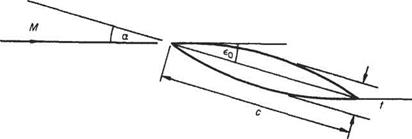 |
Fig. 6.46
was done on these sections both with symmetrical and cambered profiles and this is readily available to compare with the theory.
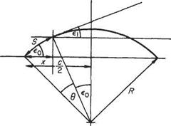
Consider the thin symmetrical aerofoil section shown in Fig. 6.46. On the upper surface x from the leading edge and the deflection of the flow from the free – stream direction is єи, and єи — —a + £o[l — (2x/c)],* so that the local pressure coefficient is
 |
6D =
and integrating gives after substituting for Єу and
Now, by geometry, and since єо is small, є0 = 2(t/c), giving
The lift/drag ratio is a maximum when, by division, D/L = a+ [^(t/c)2/a] is a minimum, and this occurs when
![]() 4 /t 21
4 /t 21
Then
![]()
1 y/3 c 0.433
For a 10% thick section (L/D)mzx = 4at a = 6.5°
Moment coefficient and kcp
 |
||
Directly from previous work, i. e. taking the moment of 8L about the leading edge:
 |
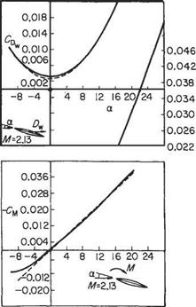 |
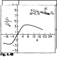
and the centre of pressure coefficient = -(См/Cl) = 0.5 as before. A series of results of tests on supersonic aerofoil sections published by A. Ferri[32] serve to compare with the theory. The set chosen here is for a symmetrical bi-convex aerofoil section of f/c = 0.1 set in an air flow of Mach number 2.13. The incidence was varied from — 10° to 28° and also plotted on the graphs of Fig. 6.48 are the theoretical values of Eqns (6.156) and (6.157).
Examination of Fig. 6.48 shows the close approximation of the theoretical values to the experimental results. The lift coefficient varies linearly with incidence but at some slightly smaller value than that predicted. No significant reduction in Cl, as is common at high incidences in low-speed tests, was found even with incidence >20°.
The measured drag values are all slightly higher than predicted which is understandable since the theory accounts for wave drag only. The difference between the two may be attributed to skin-friction drag or, more generally, to the presence of viscosity and the behaviour of the boundary layer. It is unwise, however, to expect the excellent agreement of these particular results to extend to more general aerofoil sections – or indeed to other Mach numbers for the same section, as severe limitations on the use of the theory appear at extreme Mach numbers. Nevertheless, these and other published data amply justify the continued use of the theory.
General aerofoil section
Retaining the major assumptions of the theory that aerofoil sections must be slender and sharp-edged permits the overall aerodynamic properties to be assessed as the sum of contributions due to thickness, camber and incidence. From previous sections it is known that the local pressure at any point on the surface is due to the magnitude and sense of the angular deflection of the flow from the free-stream direction. This deflection in turn can be resolved into components arising from the separate geometric quantities of the section, i. e. from the thickness, camber and chord incidence.
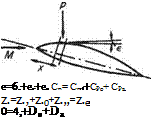
The principle is shown figuratively in the sketch, Fig. 6.49, where the pressure p acting on the aerofoil at a point where the flow deflection from the free stream is є may be considered as the sum ofpt +pc+ pa. If, as is more convenient, the pressure coefficient is considered, care must be taken to evaluate the sum algebraically. With the notation shown in Fig. 6.49;
Cp = CPt + CPc + CPa (6.158)
or
– —2 , . 6x
oCl, ~ (£t + ec + єа) —
Vm2 -1 c
 |
 |
|
which is made up of terms due to thickness, camber and incidence. On integrating round the surface of the aerofoil the contributions due to thickness and camber vanish leaving only that due to incidence. This can be easily shown by isolating the contribution due to camber, say, for the upper surface. From Eqn (6.148)
Fig. 6.49
|
i’£‘d*=f(©Id”i’d*=w=o |
Therefore
Similar treatment of the lower surface gives the same result, as does consideration of the contribution to the lift due to the thickness.
 |
This result is also borne out by the values of Cl found in the previous examples, i. e.
Now єа (upper surface) = —a and ea (lower surface) = +a
![]() CL =
CL =
![]()
![]() 4a
4a
sjM1- 1
Drag (wave) The drag coefficient due to the element of surface shown in Fig. 6.49 is
SCd = Cpe2 — c
which, on putting є = є1+єс+єа etc., becomes
6Cd = ) =. — (fit + ЄС + Ea) —
VM2 – 1 C
On integrating this expression round the contour to find the overall drag, only the integration of the squared terms contributes, since integration of other products vanishes for the same reason as given above for the development leading to Eqn (6.160). Thus
Now
2 <j) £2dx = AoJc
and for a particular section
![]()
2 ф є2 dx = kc(32c
where t/c and /3 are the thickness chord ratio and camber, respectively, and kt, kc are geometric constants.
Lift/wave drag ratio It follows from Eqns (6.160) and (6.161) that
D, Ht/cf + кф2
T = a з————– л———–
L 4 a
which is a minimum when
q2 = fct {t/cf + кф2
Moment coefficient and centre of pressure coefficient Once again the moment about the leading edge is generated from the normal contribution and for the general element of surface x from the leading edge
![]() x dx Vm2 – 1J c£ c
x dx Vm2 – 1J c£ c
_ -2 /. . x djc
Cm — , – Ф {єа + £t + єс)–
VM2 -l J с c
Now
![]() x d*
x d*
£t——-
c c
is zero for the general symmetrical thickness, since the pressure distribution due to the section (which, by definition, is symmetrical about the chord) provides neither lift nor moment, i. e. the net lift at any chordwise station is zero. However, the effect of camber is not zero in general, although the overall lift is zero (since the integral of the slope is zero) and the influence of camber is to exert a pitching moment that is negative (nose down for positive camber), i. e. concave downwards. Thus
 |
The centre of pressure coefficient follows from
fccp = 0.5(+^
and this is no longer independent of incidence, although it is still independent of Mach number.


