Threedimensional wings
5.3 All the design aims have been specified so far in terms of the nearfield of the flow; in fact, in terms of the pressure distribution over the surface. But it is often claimed that, to reach the design aims, a farfield approach, as explained in Section 3.1, would be sufficient and simpler and indeed more efficient, since it would allow the "minimisation" of the drag and the "optimisation" of the configuration, at least for inviscid flow. A balanced discussion of these claims may be found in the review by J A Bagley (1961). At subsonic speeds, the farfield approach takes note only of the spanwise lift distribution (by a consideration of the flow in the Trefftz plane). At sonic and supersonic speeds, this approach takes account also of the wavedrags. The sonic and supersonic area rules, described in Sections 4.8 and 4.9, appear at first sight to define the shape of a configuration. We have, in fact, used the general drag relation (4.140) with convenient values for the drag factors to define at least the shape of boxes into which configurations should be fitted to be aerodynamically efficient (see Fig. 4.76). But it is doubtful whether we can usefully go much further than that since designs by any of the area rules only have many shortcomings. Firstly, the drag values implied, and hence the "optimisation", may be quite inaccurate because the assumptions upon which the rules are based are not fulfilled. Even when they are, as on some slender wings (to be discussed in Section 6.7), the sonic area rule may lead to gross errors. Secondly, the shapes are not defined uniquely, and the fewer the geometrical constraints imposed, the smaller is the guarantee that the optimum shape will actually be meaningful (i. e. that it will not have negative thickness or some similar geometrically absurd feature). Thirdly, and most importantly, there is no assurance that the flow past any of the resulting shapes is physically possible: unless the pressure distribution over the surface is known and a check made whether or not a viscous region can be fitted underneath the inviscid flow (as explained in Section 4.5), we do not have a physically meaningful solution. For these reasons, the nearfield approach is indispensable. It is adopted here but this, in turn, implies that the flows and shapes obtained, however realistic, are not necessarily the best and most efficient. This is a physical dilemma which cannot readily be resolved. However, whenever possible, the farfield approach can be used to give some guidance and, in this sense, the two approaches are complementary.
In the nearfield approach, an isobar pattern over the wing surface is specified, at least over the upper surface, such as one of those shown in Fig. 5.1.
To calculate the wing shape, the RAE Standard Method with the iterative extension by С C L Sells (1974) and (1976) can be used for subcritical speeds and some linearised theories for sonic and supersonic speeds. This means that supercritical isobar patterns like case (d) in Fig. 5.1 cannot yet be dealt with. The procedure is the same as that outlined in Section 5.1 and as applied
to the case of a twodimensional aerofoil in Fig. 5.2. For threedimensional wings, the main design parameters are now not only the chordwise thickness and camber distributions of the aerofoil sections at various stations along the span but also the twist distribution a, j.(y) along the span and the planform shape itself, that is, the spanwise distribution c(y) of the chord. Since the relations for the pressure are basically made up of twodimensional terms and of kink and tip terms, where the pressure is proportional to the local source and vortex strengths, we can expect that any of the design changes needed to depart from the undesirable isobar pattern in case (a) of Fig. 5.1 will exhibit some common features. To explain these clearly in a simple form, we consider the central region of a sweptback wing of constant chord and infinite span and demand that the wing should be designed to eliminate the kink effect, i. e. the isobars should be straight and parallel from the sheared part of the wing right up to the centre line.
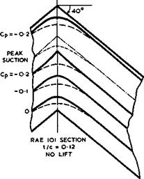
Regarding thickness effects at zero lift, we recall that the velocity at the centre section of a wing with constant sections is always higher than that on an infinite sheared wing behind the crest and lower upstream of it, as is demonstrated by the typical example in Fig. 4.19. To remedy this, and to reach the same velocities as over the sheared part of the wing, it can readily be seen that the thickness and surface slope should be reduced over the rear part of the centre section and increased over the front part, that is, the position of maximum thickness should be shifted forward. This implies that the section modifications should all look like that in the example*) in Fig. 5.17 (1) (ba-
|
|
( I ) SAME PRESSURE DISTRIBUTIONS AT ZERO LIFT
 |
(2) SAME CHORDWISE LOADINGS AT CL«0-3
sic section RAE 101, q> = 35°, t/c = 0.1, M_ = 0.85). This has been calculated from (4.88) with appropriate compressibility factors. Such thickness modifications have been first proposed and determined by D Ktlchemann (1974).
F Ursell (1949) has rewritten (4.86) in the form
*) . .
If an arbitrary velocity distribution is chosen, the section shape obtained may not be physically sensible, even in this nearfield approach: the application of (4.88) will lead to aerofoils that close at the trailing edge, but it does not guarantee positive thickness at all points – the contours of the upper and lower surfaces may cross each other. We also note that such section modifications happen to make the cross-sectional area distribution "smoother".
!!t = / 3zt(x,) dx’ vx(x»°>0)
dx ° irf(^) J Эх x – x’ – Vq cos ¥> f (<P) (5.17)
and obtained an explicit expression for the section shape of a wing having a specified velocity distribution vx(x) at its centre section:
and f(<p) is defined by (4.87). Explicit solutions can be obtained also for special aerofoil sections, such as the biconvex circular-arc section (see S Neumark (1947), D Kiichemann (1947)). This leads to some simple approximate formulae for estimation purposes, derived for small angles of <p but applicable up to angles beyond about 60°: the thickness-to-chord ratio is to be changed roughly according to
(tje) = 1 – (it – l)(<p/ir)2 ; (5.20)
and the forward shift of the position of maximum thickness is roughly
x/c = <p/2tt ; (5.21)
where the suffix 0 denotes the basic section on the sheared part of the wing.
It should be noted that, although a wing designed in this way may have straight isobars and thus delay the onset of supercritical flow, the central region will still, in general, carry a non-zero normal-pressure drag. The pressure distribution of an infinite sheared wing will give zero drag only on the shape of the sheared-wing section itself and not on the modified section. It is possible, however, to design centre-section shapes which have a low or even zero drag. J Weber (unpublished; see J A Bagley (1961)) has calculated the centre-section shape for which the velocity increment is constant along the chord, so that the local sectional drag is zero for this closed section. This is a perfectly reasonable shape defined by
where 8 is given by (5.19). But the drag of sections along the span for у > 0 may then be greater than before the modification and the overall drag
in the central region may be the same as before. These matters have not yet been investigated in detail.
Regarding next lift effects on wings of zero thickness, we recall that the load along the centre section of a flat wing is always higher over the rear part and lower over the front part than that over an infinite sheared wing,
as is demonstrated by the typical example in Fig. 4.23. To remedy this, and to reach the same loading as over the sheared part of the wing, it can readily be seen that the chordwise slope of the camberline of the centre section must be increased towards the leading edge, that is, the centre section should have negative camber and positive twist. This means that the centre modifications should all look like that in the example in Fig. 5.17 (2) (C^ * 0.3;
Ф = 35°; Mq = 0.85; with thickness of basic RAE 101 section with t/c =0.1 superimposed). As usual, we consider thickness and camberline modifications to be additive, to a first order.
The application of this kind of camber and twist has been proposed by D Kiiche – тпяпп (1950), and the shape for the particular aerofoil considered here has already been derived in Section 4.4 and is given by (4.97). G G Brebner (1952) provided analytical solutions for a whole family of camberZines with loadings of the form
i(x, y) – sin irn jcj X j + C2 J, (5.23)
where and C2 are constants related to the maximum camber and to its
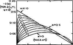
chordwise position. The parameter n(<p, y) is given by (4.105) and the parameter m, with 0 $ m $ 1, describes the shape of the camberline. This family of camberlines is shown in Fig, 5.18. In twodimensional flow, the case
 LIVE GRAPH
Click here to view
|
O 0*2 0-4 x/c О 6 0 8 l-o Fig. 5.18 The shapes of Brebnerfs camberlines |
m = 0 corresponds to a uniform loading along the chord and is thus the same as that of the NACA camberline designated a = 1 (see I H Abbott et a7.(1945)); and the case m = 1 corresponds to a flat plate. At the centre of sweptback wings, the case m = corresponds to (4.97). Brebner derived the complete set of aerodynamic properties for this family, including expressions for the no-lift angle and the centre of pressure. These camberlines may be used for design purposes, within the method described in Section 4.4, when the shape of the section on the sheared part of the wing is not flat but cambered, as it will usually be. Further work on designing cambered wings to give uniform loading along the span has been done by T Kawasaki (1965) and by T Kawasaki &
M Ebihara (1966).
An extensive framework of methods for the design of cambered wings with subsonic edges in inviscid flow at sonio and supersonic speeds has been developed and reviewed by R C Lock & J Bridgewater (1967). In these methods, the perturbations in the flow are assumed to be small and shockwaves are not admitted. Thus wings with supercritical pressure distributions cannot be treated. The camberlines and distributions obtained are of the same type as Brebner’s solutions for subsonic speeds. Since centre and tip effects may be very pronounced at sonic and supersonic speeds, camber and twist needed to compensate for them may be large. Modifications of the thickness and camber shapes at subcritical speeds, as indicated in Fig. 5.17 may also be quite considerable. This’ must imply that the supercritical development of the flow past such shapes may not be the same as that on the corresponding twodimensional aerofoil, even if they all start from the same subcritical pressure distribution. These matters have not yet been resolved.
The shape of the centre section of swept tapered wings with a linear chordwise load distribution has been calculated by J C Cooke (1958). G M Roper (1959) has developed a method for determining camber shapes to give a specified loading over sweptback wings with subsonic edges at supersonic speeds. Quite generally, thickness modifications and the application of camber and twist can be carried out all along the span of a swept wing. At subcritical speeds, the tip regions can again be treated like the centre section of a halfwing of opposite sweep. If the velocity increments due to thickness at the tip are to be equal to those of an infinite sheared wing at subsonic speeds, the resulting shape will have a considerably larger thickness-to-chord ratio than the original section because of the reduction factor 0.7 in (4.91), as explained in Section 4.4. However, the nose thickness then becomes rather small and the trailing-edge angle large since the position of the maximum thickness will be shifted backwards, according to (5.21). If t/c is kept the same at the tip, then the velocity will be reduced and hence some isobars will be closed before they reach the tip. An alternative method of improving the tip region which leaves the thickness distributions of the sections unaltered, is to aurve the leading edge (parabolically, say) from some point on the leading edge inboard of the tip (which may be about 1/4 of the local wing chord away) to a stream – wise tip at the trailing edge, in the manner indicated in Fig. 4.66, for example. The idea behind such a shape, as proposed by J Weber (1949), is to produce the unavoidable tip thrust (see e. g. Fig. 4.33) not by increasing the suction but by reducing the positive pressure near the attachment line along the leading edge. The isobars may then roughly follow the planform shape and acquire higher angles of sweep in the tip region than on the sheared part of the wing, as sketched in cases (b) and (c) in Fig. 5.1.
All these design modifications can be applied to the wing at one specific design point only, i. e. specific values of Cl and Mq, for a given planform. Further, part of the (often large) angle of twist is needed simply to compensate for the non-uniformities in the spanwise loading, that is, to load up the central part and to unload the tip regions. This purpose can also be achieved by a planform modification, for example, by reducing the chord in the central region, as compared with an elliptic planform, say, and increasing it in the tip regions. In principle, this has the considerable advantage that the span – wise lift distribution CL(y) can be designed to have a given shape at all CL-values within the linear range. Cl may be kept constant along the span, if so desired. This implies, in turn, that camber and twist are then required only to look after the chordwise loading. Planforms to give constant Cl may also have a beneficial effect on the longitudinal stability and on the stalling characteristics.
Planform modifications as a possible means of swept wing design were proposed as soon as the peculiarities of the loading over sweptback wings (see e. g.
 |
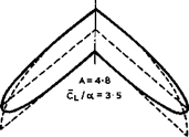 |
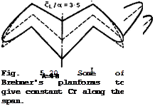
Fig. 4.24) were recognised, by Lemme and Luckert (unpublished AVA Reports (1943) and (1944); see R Seiferth (1947)). Similar planform modifications were incorporated into the Republic XF-91 aircraft (see R McLarren (1949)), but no results are available. The early methods were not very accurate in taking account of the centre and tip effects, but now better methods such as that described in Section 4.4 can be used to calculate the planform shape. In particular, (4.56) or the more general form (4.81) can be regarded as a relation for determining c(y) for given values of С^(у), a(y), and <p. Since the sectional lift slope a depends on y/c and thereby on the unknown chord, the solution can only be obtained by iteration in successive approximations, but this presents no problems and the iteration converges rapidly. The aspect ratio of the wing and the overall C^-value cannot be prescribed but come out at the end. This method has been applied by D KUchemann (1950), and some results have already been shown in Fig. 4.21. Many applications have been worked out by G G Brebner (1954) and (1956), and some of his results are reproduced in Figs. 5.19 and 5.20. He found that sweptback wings acquire inverse taper in the central part as the aspect ratio and the angle of sweep are increased. For example, for a wing with constant C^, inverse taper is just avoided when A = 2 for <p = 40°, and when A = 1 for q> = 60°. For higher values of A and/or ф, there comes a point where the chord at the centre is zero. This happens, for instance, when A = 10 and <p = 60°. We find as a general result that the conventional planform taper of unswept wings is detrimental on sweptback wings and only reinforces the shortcomings. The opposite applies to sweptforward wings, where conventional taper has a beneficial effect.
Fig. 5.19 Some of Brebner’s plan – forms to give constant CL along the span on sweptback wings. <p = 40°
Fig. 5.20 shows some unconventional planforms which also give a constant CL – value along the span. These include a sweptforward wing. It seems strange that forward sweep has been largely neglected so far, even though an aircraft with sweptforward wings, the JU 287 with 4 turbojet engines, was designed by H Wocke and flown successfully as early as 1944. Forward sweep has many obvious aerodynamic and structural advantages, and it should be possible to overcome difficulties in the aeroelastic behaviour. The other planforms in Fig. 5.20 have not yet been applied in practice either; they deserve to be taken more seriously. Note that the overall lift slope CL/a of the sweptforward wing of A = 3>3 is the same as that of the sweptback wing of A = 4.8. The nominal (midchord) angle of sweep is the same for all planforms shown in Figs. 5.19 and 5.20, but this does not mean that the critical Mach numbers and the wing characteristics beyond that need be the same. In the absence of any detailed information, we cannot yet say whether unconventional planforms, if fully developed, would offer significant advantages over the conventional sweptback wing.
In two of the cases in Figs. 5.19 and 5.20, alternative planform shapes have been drawn (dotted lines) where only the beading edge is curved and the trailing edge is kept straight. To a first order, these planforms have the same uniform CL_distribution and only second-order effects, taking account of varying sweep angles near the tips, are likely to reduce Cl a little in the tip regions. These planform shapes with straight trailing edges may have constructional advantages and may ease the installation of high-lift devices.
As it happens, this curved leading edge has the kind of shape which has been described above as being beneficial for the isobar pattern due to thickness.
We now find that it is also beneficial for lifting subsonic wings. Furthermore R C Lock (1957) and (1961) has derived similar curved leading-edge shapes for transonic speeds to fulfil the condition that the behaviour of the pressures near the leading edge should be the same along the span, which should make the actual suction peaks on rounded sections roughly the same and thus improve on the flow which otherwise has high tip suction peaks, implied in Figs. 4.67 and 4.68. Thus it turns out that a curved tip shape may be a desirable design feature in several respects.
In a practical design, it is likely that the various means for modifying thickness, camber, twist, and planform shape may be combined to obtain a satisfactory overall solution. A useful survey of factors which affect the choices to be made in the design of a threedimensional sweptback wing for high-subsonic speeds has been given by A В Haines (1968).
One further possibility should be mentioned, namely, the application of thickness taper (see e. g. 0 Holme & F Hjelte (1953), J Weber (1954), К W Newby
(1955) ). It has been shown that a reduction of the thickness from the centre towards the tips may cause a significant reduction of the velocity increments because of the more threedimensional nature of the flow. As applied by К W Newby (1958), thickness taper may be combined with a CL~distribution which increases towards the tips and yet produces fully-swept isobars. This should bring the vortex drag closer to its minimum value. Again, planform modifications can be combined with camber and twist to achieve a low value of the vortex drag, and wings with minimum drag due to lift in supersonic flow have been designed by I Ginzel & H Multhopp (1960). However, these efforts to reach the lowest vortex drag seem rather misdirected, ever since H Glauert
(1926) and J Hueber (1933) showed that, for low speeds, departures from the optimum shape (e. g. by using a straight-tapered instead of an elliptic plan – form) did not necessarily lead to large increases in vortex drag. J A Bagley
& J A Beasley (1959) obtained similar results for a series of sweptback wings at low supersonic speeds. We may conclude from this that it is more important to design for realistic pressure distributions for viscous flows and for efficient isobar patterns.
|
|
|
Fig. 5.21 Isobar patterns near the centre of a sweptback wing. Dashed lines: constant section; full lines: modified sections |
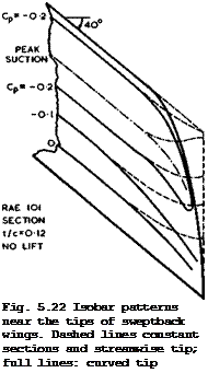 |
We can now turn to вот experimental evidence obtained to test some of the design methods outlined above. There is as yet no comprehensive set of experiments and we refer only to a few early results which concern specific points in the design procedure. Figs. 5.21 and 5.22 show that the thickness modifications described above work quite well near the centre of a sweptback wing at low speeds, and that a curved tip shape is also quite effective. In these tests, by J Weber (1949), thickness modifications of the sections near the wing tip were also tested and proved in the main successful. With the more recent calculation methods by J Weber and С C L Sells, more accurate results can be obtained, but compressibility effects still present a problem.
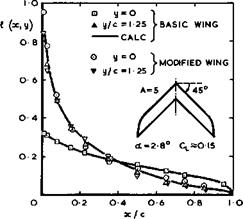
Fig. 5.23 shows corresponding results for the chordwise loadings at the centre of a sweptback wing at low speeds, and it will be seen that the camber and twist applied to the modified wing do indeed compensate for the large centre effect and bring the loading back to that of the sheared part of the wing.
If anything, the effect is slightly overestimated and the suction peak near the apex of the modified wing is a little too high. But more recent evidence has shown that this tendency may disappear and may, in fact, be reversed by compressibility effects as the Mach number is increased.
Planform modifications to affect the spanwise loading and also the chordwise loading, when combined with camber and twist, have been studied experimentally by G G Brebner (1965) and shown to be effective at low speeds. A very
LIVE GRAPH
Click here to view
|
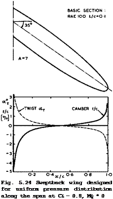
stringent test was carried out by D S Woodward & D E Lean (1971) on a wing designed by the RAE Standard Method to have uniform spanwise loading and the same ohordwise loadings everywhere at a C^-value close to the Ст^у-value
 LIVE GRAPH
Click here to view
|
|
|
Fig. 5.25 Isobar patterns over the upper surface of the sweptback wing of Fig. 5.24. After Woodward & Lean (1971) |
of the corresponding twodimensional aerofoil section (C^ = 0.8), again at low speeds. The planform and the camber and twist distributions along the span are shown in Fig. 5.24. These are typical for this kind of requirement. Some results in Fig. 5.25 demonstrate that the design has been largely successful in straightening out the isobars over the upper surface, not only at the design lift coefficient of Cl = 0.8 but also below it at Cl = 0.4. There are again slightly higher suction peaks near the apex, which may also be connected with the difficulty encountered in placing the thickness distribution around the highly-curved camberline, and in achieving a turbulent flow everywhere in the model tests. Woodward & Lean also succeeded in correlating CLmax-values in two-and threedimensional flows and also sectional stall patterns. Some uncertainties arose, as to be expected, when viscous effects led to strong span – wise influences.
Further interesting experimental evidence on a cambered and twisted wing and on thickness effects at high-subsonic Mach numbers has been provided by A В Haines & L N Holmes (I960). A detailed description of the aerodynamic design of a typical subsonic aircraft (VC 10) has been given by J A Hay
(1962) . Early work on the design of transonic aircraft has been described by M В Morgan (1960) and more recent approaches to this problem by L T Goodmanson
(1971) . A detailed appraisal of methods for designing wings for subsonic flight has been made by W Loeve (1974). For subcritical flows, the iterative design technique for thick cambered wings by С C L Sells (1976) is probably the physically most realistic and the numerically most accurate of all methods. Other design work, especially that for aircraft to fly at higher speeds, has been concerned mainly with wing-fuselage combinations. This will be discussed in Section 5.6.
It should be clear from the foregoing that the actual design of sweptwings still requires a great deal of skilful engineering ingenuity, there are numerous design parameters, aspects, and desiderata, quite often conflicting;
Next Page
251
and not enough is yet known about what the aerodynamic design criteria should be. The success or otherwise of a design therefore depends to a large extent on the designer’s knowledge of the physics of the flow, and no improvements in numerical and experimental design tools are ever likely to dispose of the need for physical insight. On the other hand, a good understanding of the flow phenomena involved has led to successful designs even in the early days when the available design tools were still rather poor. An example of this kind is the modification of the wing of the Avro Vulcan aircraft by К W Newby (1955), which effectively converted the original delta wing into a wing where sweep effects were successfully exploited. Another early example where the same design principles were applied successfully was the Vickers V 1000 intercontinental airliner project, which would have preceded the generation of Boeing 707 and DC 8 aircraft by a substantial number of years had it not been cancelled for short-term political reasons in 1955 (see Sir George Edwards (1974)). Yet another instructive example is the design of the wing of the Handley-Page Victor aircraft in the late 1940s, which brought in many facets that anticipated what are now regarded as typical features of a new "supercritical wing".
The Victor aircraft was designed to carry a considerable load over a range of about 5 000 km at a cruising Mach number just below 0.9, with a safe flight envelope extending to near-sonic speed. The main object of the design by G H Lee (1950; also private communication) was to combine sweep effects usefully with turbojet propulsion in a clean shape, the engines to be installed within the wing and not in separate pods, and also to combine the required cruise performance with a good airfield performance. The first choice made was the adoption of a orescent or cranked wing planform, that is, of a shape where the inner part of the wing has a longer chord and a higher angle of sweep of the leading edge than the outer parts of the wing. Such planforms were first proposed by R E Kosin and incorporated in the design of the Arado Ar 234 V16 aircraft in 1944. The objective is to achieve high isobar sweep in the middle part of the wing at high speeds and to improve tip-stalling behaviour at low speeds (see also R Hills & D KUchemann (1947) , D Ktichemann & J Weber (1947), G G Brebner (1953)). Thus the angle of sweep of the с/4-line was decreased from 53° for the centre part to 22° for the tip parts of the wing, with 35° sweep over an intermediate part, on a wing with a moderately high aspect ratio of 6 and taper ratio of 1:4. The next design aim was to keep the critical Mach number constant along the span at the cruise of about 0.3.
Thus the shapes of the wing sections were specifically designed with suitable distributions of thickness as well as camber and twist to achieve straight isobars over the upper surface of the wing, with an angle of sweep of the peak – suction line higher than the geometric angle; i. e. C m£n was located at about 0.3 c at the wing root and at about 0.6 c at the tip. The value of t/c itself proved to be the most powerful design parameter and this led to a large thickness taper along the span, from t/c = 0.16 at the wing root to t/c = 0.04 at the tips. This, in turn, not only brought some desired structural advantages, but also provided a large stowage volume for engines and undercarriage near the wing root, consistent with the basic crescent-wing concept. The engine installation immediately outboard of the fuselage saved nacelle drag and avoided any serious yawing moment from a cut engine, thus easing the design requirements for the fin and the rudder. In addition, the suction forces associated with the leading-edge air intake in the wing root (see Section 3.7) could be integrated with those over the basic wing to help to establish the desired isobar pattern. This is an essential feature of the design, since the basic planform runs counter to those needed for constant C^, as in Figs. 5.19 or 5.25. The design of the threedimensional swept air-intake needed special care to avoid local regions of high velocities and hence low critical Mach numbers as well as high adverse pressure gradients and flow
Previous Page
252
separations. The velocity increments are always higher at the rearmost part than at the leading part of intake lips, whether the intake is staggered in sideview or swept in planview. These matters are explained in D KUchemann &
J Weber (1953), Sections 4-8 and 5-3, and the resulting guidelines for design were applied. By exploiting all these means, a very satisfactory aircraft design was achieved, with a high critical Mach number together with an orderly flow at supercritical Mach numbers. At low speeds, a forward extension of 0.2 c on the outer wing with a drooped nose was needed to give acceptable stalling characteristics. Where the Victor design differs from a more modern supercritical wing is in the treatment of the fuselage: there is no hump on top of the fuselage in an attempt to pull the isobars over the fuselage in a swept manner, which is an obvious design feature. Instead, another solution was adopted where most of the isobars close at the side of the fuselage, so that the remaining unswept isobars across the body give the same critical Mach number as that on the wing. This was possible because the main wing spar box was so far forward that it could cross the fuselage well ahead of the centre of gravity of the aircraft, leaving all the movable payload and the fuel conveniently behing the wing spar in a fuselage of minimum cross-section, and allowing the wing to be mounted centrally on the fuselage. The resulting clean intersection and curved junction shapes helped to achieve the desired isobar pattern (see also Section 5.6).


