Uniform Lifting Surface
So far, our aeroelastic analyses focused on rigid wings with a flexible support. These idealized configurations provide insight into the aeroelastic stability and response, but practical analyses must take into account flexibility of the lifting surface. That being the case, in this section, we address flexible wings, albeit with simplified structural representation.
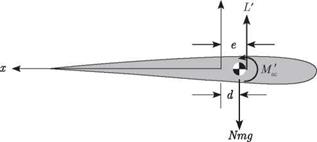
Consider an unswept uniform elastic lifting surface as illustrated in Figs. 4.11 and 4.12. The lifting surface is modeled as a beam and, in keeping with historical practice in the field of aeroelasticity, the spanwise coordinate along the elastic axis is denoted by y. The beam is presumed to be built in at the root (i. e., y = 0, to represent attachment to a wind-tunnel wall or a fuselage) and free at the tip (i. e., y = £). The y axis corresponds to the elastic axis, which may be defined as the line of effective shear centers, assumed here to be straight. Recall that for isotropic beams, a transverse force applied at any point along this axis results in bending with no elastic torsional rotation about the axis. This axis is also the axis of twist in response to a pure twisting moment applied to the wing. Because the primary concern here
|
z
Figure 4.12. Cross section of spanwise uniform lifting surface |
is the determination of the airload distributions, the only elastic deformation that influences these loads is rotation due to twist about the elastic axis.


