Winglets
After examining results from the Program PRANDTL, it is desirable to make the AR of a wing as large as possible. However, there are practical limitations to increasing the wing span and, hence, the AR. The larger the span, the greater the length of the cantilever beam represented by the half-wing and the greater the structural problems. Also, a large wing span makes ground-maneuvering and parking of the aircraft difficult.
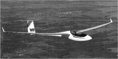
Aircraft of all types have been designed with winglets instead of increased span. For example, Fig. 6.27 shows a modern sailpane with winglets. In this application, the benefit comes without increased span. (Span is limited by international competition rules; the glider shown is a 15-meter-span “standard class” racing machine.) The glide ratio is increased by at least one L/D point, from 42 to about 43, by this modification. The equivalence of glide and L/D ratios is explained in Chapter 1.
Winglets increasingly are used in commercial aviation because the improvement in effective AR leads directly to reduced operational costs. The benefits result from the influence that the winglets have on the behavior of the tip vortices and the interaction of these vortices with the wing flow field. Thus, they originally were called vortex diffusers by the inventor, Richard Whitcomb of NASA (Whitcomb, 1976, Flechner, etal, 1976). There is evidence that the basic concept already was known before manned flight actually was accomplished, but Whitcomb receives the credit for the winglet in its modern form.
The winglet is a miniature wing of precise shape that is set nearly vertically at the tip of the main wing, with the winglet leading edge inboard of the trailing edge. The corner is carefully faired. The winglet reduces drag in two ways as follows:
1. The relative wind at the winglet, which is the vector sum of the oncoming stream and the flow around the wing tip, acts on the winglet so as to produce a force component in the negative drag (i. e., thrust) direction.
2. The presence of the winglet distorts the shape of the wing-tip vortex and modifies the strength of the trailing-vortex sheet.
|
Figure 6.27. Schleicher ASW-24B with winglets. |
Winglet design currently is accomplished by means of numerical programs such as the panel methods discussed in the previous sections. As always, we must consider the tradeoff between reduced induced drag and additional form drag resulting from the increased surface area. The numerical results then are verified by careful wind-tunnel testing, and an iterative process leads to the best compromise between performance needs across the operational speed range of the aircraft.


