Airload Distribution
It has been observed that the spanwise-lift distribution can be determined as
L = qca(ar + в) (4.66)
where we recall from Eq. (4.52) that
в = (ar + ar) [tan(Xl) sin(Xy) + cos(Xy) – 1] (4.67)
and where ar is given in Eq. (4.48). If the lifting surface is a wind-tunnel model of a wing and is fastened to the wind-tunnel wall, then the load factor, N, is equal to unity and ar can be specified. The resulting computation of L is straightforward.
If, however, the lifting surface represents half the wing surface of a flying vehicle, the computation of L is not as direct. Note that the constant ar is a function of N. Thus, for a given value of ar, there is a corresponding distribution of elastic twist and a particular airload distribution. This airload can be integrated over the vehicle to obtain the total lift, L. Recall that N = L/ W, where W is the vehicle weight. It is thus apparent that the load factor, N, is related to the rigid angle of attack, ar,
 |
|
through the elastic twist angle, в. For this reason, either of the two variables ar and N can be specified; the other then can be obtained from the total lift L. Assuming a two-winged vehicle with all the lift being generated from the wings, we find
 |
|
Because N = L/ W, this expression can be divided by the vehicle weight to yield a relationship for N in terms of ar and ar. This relationship then can be solved simultaneously with the preceding expression for ar, Eq. (4.48), in terms of ar and N. In this manner, ar can be eliminated, providing either a relationship that expresses N in terms of ar, given by
or a relationship that expresses ar in terms of N
These relationships permit us to specify a constant ar and find N(q) or, alternatively, to specify a constant N and find ar(q). We find that N(q) starts out at zero for q = 0. Conversely, ar(q) starts out at infinity for q = 0. The limiting values as q ^ qD depend on the other parameters. These equations can be used to find the torsional deformation and the resulting airload distribution for a specified flight condition.
The calculation of the spanwise aeroelastic airload distribution is immensely practical and is used in industry in two separate ways. First, it is used to satisfy a requirement of aerodynamicists or performance engineers who need to know the total force and moment on the flight vehicle as a function of altitude and flight condition. In this instance, the dynamic pressure q (and altitude or Mach number) and ar are specified, and the load factor N or total lift L is computed using Eq. (4.70).
A second requirement is that of structural engineers, who must ensure the structural integrity of the lifting surface for a specified load factor N and flight condition. Such a specification normally is described by what is called a V-N diagram. For the conditions of given load factor and flight condition, it is necessary for structural engineers to know the airload distribution to conduct a subsequent loads and stress analysis. When q (and altitude or Mach number) and N are specified, ar is then determined from Eq. (4.71). Knowing q, ar, and N, we then use Eq. (4.48) to find ar. The torsional deformation, в, then follows from Eq. (4.67) and the spanwise-airload
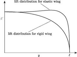
Figure 4.14. Rigid and elastic wing-lift distributions holding ar constant
 distribution follows from Eq. (4.66). From this, the distributions of torsional and bending moments along the wing can be found, leading directly to the maximum stress in the wing, generally somewhere in the root cross section.
Observe that the overall effect of torsional flexibility on the unswept lifting surface is to significantly change the spanwise-airload distribution. This effect can be seen as the presence of the elastic part of the lift coefficient, which is proportional to в(y). Because this elastic torsional rotation generally increases as the distance from the root (i. e., out along the span), so also does the resultant airload distribution. The net effect depends on whether ar or N is specified. If ar is specified, as in the case of a wall-mounted elastic wind-tunnel model (N = 1) or as in performance computations, then the total lift increases with the additional load appearing in the outboard region, as shown in Fig. 4.14.
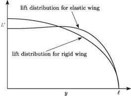
In the other case, when N is specified by a structural engineer, the total lift (i. e., area under L versus y) is unchanged, as shown in Fig. 4.15. The addition of lift in the outboard region must be balanced by a decrease inboard. This is accomplished by decreasing ar as the surface is made more flexible.
 Figure 4.15. Rigid and elastic wing-lift distributions holding total lift constant
All of the preceding equations for torsional divergence and airload distribution were based on a strip-theory aerodynamic representation. A slight numerical improvement in their predictive capability can be obtained if the two-dimensional lift-curve slope, a, is replaced everywhere by the total (i. e., three-dimensional) lift – curve slope. Although there is little theoretical justification for this modification, it alters the numerical results in the direction of the exact answer. Also, it is important to note that the lift distributions depicted in Figs. 4.14 and 4.15 cannot be generated with strip-theory aerodynamics because strip theory fails to pick up the dropoff of the airload to zero at the wing tip caused by three-dimensional effects. An aerodynamic theory at least as sophisticated as Prandtl’s three-dimensional lifting-line theory must be used to capture that effect. In such a case, closed-form expressions such as those of Eqs. (4.70) and (4.71) cannot be obtained; instead, it is necessary to use numerical methods to find N as a function of ar or ar as a function of N.


