Applications of Pressure Sensitive Paint
9.1. Low-Speed Flows
9.1.1. Airfoil Flows
PSP measurements are challenging in low-speed flows where a change in air pressure is very small. The major error sources, notably the temperature effect, image misalignment and CCD camera noise, must be minimized to obtain acceptable quantitative pressure results at low speeds. Brown et al. (1997, 2000) made baseline PSP measurements on a NACA 0012 airfoil at low speeds (less than 50 m/s). The experiments systematically identified the major error sources affecting PSP measurements at low speeds and developed the practical procedures for minimizing these errors. After all efforts were made to reduce the errors, reasonably good pressure results were obtained at speeds as low as 10 m/s.
Brown (2000) conducted three sets of tests (Cases I, II and III) with increasingly improved instrumentation arrangement and data processing. All the tests were made in The NASA Ames Research Test Facility Wind Tunnel having a 12-in high, 12-in wide and 24-in long test section. The Mach number ranged from 0.02 to 0.4. PSP measurements were conducted on an unswept stainless steel NACA 0012 airfoil with a 3-in chord and 9-in span. The airfoil was mounted vertically, and there is a 1.5-in gap between the airfoil’s edges and the top/bottom of the test section. Sixteen mid-span pressure taps (0.048-in diameter) were machined into the upper surface of the airfoil. Each test case was conducted consistently using the same test equipment. Images were obtained using a 14-bit Photometrics CH250 CCD camera with a Melles Griot filter (650+20 nm) attached to a 50-mm Nikor lens. Data were collected on a PC using associated Photometrics imaging software. Two Electrolite UV lamps provided illumination for PSP. Pressure tap measurements were performed with differential pressure meters connected to the airfoil via Tygon tubing. The airfoil was coated with FIB-7 basecoat and PtTFPP/FIB-7 PSP developed by the University of Washington. The white basecoat provided surface scattering to enhance the luminescent emission received by the camera. Application of the basecoat and PSP was performed using a commercial spray air gun. The
basecoat was lightly buffed to reduce surface roughness. The sufficiently thick PSP topcoat applied to the basecoat was insured to be as uniform as possible. After completing the PSP application, a hot-air gun was used to raise pSp above its glass transition temperature of about 70oC. This annealing process reduced the temperature sensitivity of PSP.
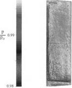
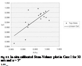
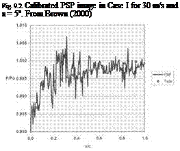
The first set of tests (Case I) provided useful PSP testing experience to identify the potential problems. The airfoil was secured onto the tunnel test section with the angle of attack of 5o. The camera and two UV lamps were secured onto a rigid double U-frame surrounding the test section mounted on the ground floor by bolts, which were approximately 18 inches away from the test section. The camera viewed perpendicularly the airfoil on which ten registration marks were placed for image registration. The total thickness of the basecoat and PSP was about 34 |am and the roughness of PSP was about 2.6 |am. The tests were run at 10, 20, 30, 40 and 50 m/s. For each tunnel run period, the tunnel settling temperature was recorded just priori to and just after image acquisition. The temperature change was within 0.17oC during a single period of image acquisition, depending on the flow velocity. The typical results for a speed of 30 m/s and the angle of attack of 5oare shown in Figs. 9.1-9.3. Figure 9.1 is the in-situ Stern-Volmer plot for PSP obtained using pressure tap data, indicating a large variation and a poor correlation between the luminescent intensity and pressure. The corresponding PSP image is shown in Fig. 9.2, where flow is from left to right. Although the low-pressure region near the leading edge is visible in the PSP image, apparent striation patterns and granular features corrupt the quality of the PSP data. This random spatial noise can be clearly seen in the chordwise pressure distribution at the mid-span, as shown in Fig. 9.3. The PSP data at speeds of 10, 20, 40 and 50 m/s had similar noise patterns.
Several problems were identified that might contribute to the large spatial noise. First, scratches on the tunnel plexiglass wall caused the streaky patterns. Secondly, PSP suffered from a considerable thickness variation due to poor application of the paint. The effect of the surface roughness could not be completely corrected using the image registration technique for the non-aligned wind-off and wind-on images. The third problem was related to model motion with respect to the lamps. Since the lamps were fixed on the ground floor, the test section underwent a lateral oscillation estimated to be on the order of 10 Hz relative to the lamps. If the model moved in a non-homogenous illumination field, the effect of the motion could not be corrected using the image registration technique. Also, this problem exaggerated the second problem associated with the surface roughness. Note that these problems might not be serious for PSP measurements in high subsonic, transonic and supersonic flows.
In Case II tests, a new test section plexiglass wall was installed to replace the scratched one. The model was cleaned and repainted carefully; thus, the roughness of the PSP layer was reduced to 0.89 |am from 2.6 |am in Case I. In order to reduce the relative motion between the model and lamps, a new mounting structure for the camera and lamps was designed and constructed, which was secured to the test section rather than the ground floor. Therefore, the lateral and vertical shifts in the image plane due to the motion were reduced to 0.43 and 0 pixels from 2.41 and 1.9 pixels in Case I, respectively. In addition, to reduce the
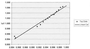
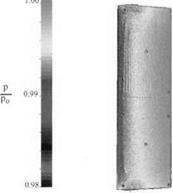
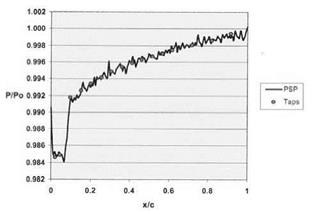
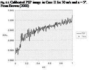
temperature change between the wind-off and wind-on images, the experimental procedure was revised such that the tunnel was run for one hour and the wind-off image was taken immediately after the wind-on image. In this way, the temperature distribution on the model in the wind-off case was close to that in the wind-on case. Figures 9.4-9.6 show results obtained in Case II tests for a speed of 30 m/s and the angle of attack of 5o. The in-situ Stern-Volmer plot in Fig. 9.4 has a better linearity and an improved correlation with the pressure tap data. The PSP image in Fig. 9.5 is also considerably improved, clearly showing not only a correct chordwise pressure profile, but also the 3D effect near the airfoil edges. The pressure tap gutter lines are also visible in the image since the gutter line epoxy has a different thermal conductivity from the stainless steel such that a small temperature difference exists. As shown in Fig. 9.6, the chordwise pressure distribution at the mid-span clearly shows a reduced noise level compared to the corresponding result in Case I.
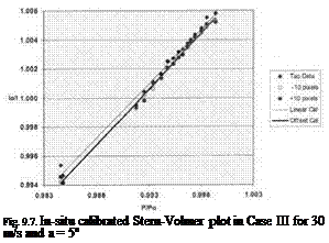
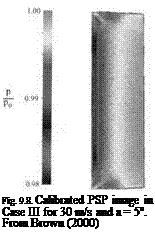
In Case III tests, careful application of PSP led to a further reduction of the paint roughness to 0.46 pm. To increase the statistical redundancy in image registration, all 16 pressure taps were used in images as registration marks, in addition to the original eight registration marks applied to the paint surface. For better in-situ calibration of PSP, 32 ‘virtual pressure taps’ located at 10 pixels above and below the spanwise location of the actual taps were created and used in images under the assumption of two-dimensionality of flows near the mid-span. As shown in Fig. 9.7, it was found that the use of the additional virtual taps provided an accuracy of 10% better than that achieved by using the actual taps only in least-squares estimation for in-situ calibration. The results of Case III tests are shown in Figs. 9.7-9.9 for a speed of 30 m/s and the angle of attack of 5o. Overall, the results indicate the improved quality of the PSP data and a reduced noise level compared to Case II.
The valuable lessons learned from this study of low-speed PSP measurements are summarized as follows. (1) Vibration and model movement with respect to cameras and lamps must be minimized to reduce the image registration error. (2) The temperature-induced errors must be minimized. Not only the tunnel test section, but also the model surface should reach a stable equilibrium state of temperature priori to acquisition of the wind-on images. It is highly suggested that the wind-off image should be acquired immediately after the corresponding wind – on image as soon as the tunnel is shut down. (3) The quality of application of both the basecoat and PSP topcoat to a surface is critical and the paint roughness must be minimized to obtain good results at low speeds. (4) In-situ PSP calibration utilizing a sufficient number of pressure taps is required to eliminate the systematic errors and obtain quantitative results. (5) Image registration is critical to reduce the spatial noise. (6) Scientific-grade CCD cameras (14 and 16 bits) should be used, and averaging a large number of images should be performed to reduce the photon shot noise and other random noises. Note that some of the above procedures for controlling the error sources are not generally applicable to large production wind tunnels.
|
|
|
|
 |
|
|
|
Fig. 9.4. In-situ calibrated Stern-Volmer plot in Case II for 30 m/s and a = 5o |
|
|
 |
 |


