Axisymmetric, Incompressible Flow around a Body of Revolution
7.1 Introduction
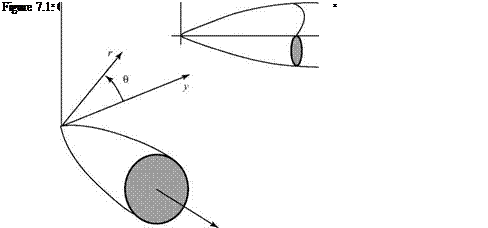
The flow considered in this chapter is assumed to be steady, incompressible, inviscid, and irrotational. The body immersed in the flow is assumed to be a body of revolution at zero angle of attack. An understanding of incompressible flow around bodies of revolution at zero or small angle of attack is important in several practical applications, including airships, aircraft and cruise-missile fuselages, submarine hulls, and torpedoes, as well as flows around aircraft engine nacelles and inlets. This type of flow problem is best handled in cylindrical coordinates (x, r), as shown in Fig. 7.1. Recall that r and 0 lie in the y-z plane.
Because the flow fields discussed in this chapter are axisymmetric, the flow properties depend on only the axial distance x from the nose of the body (assumed to be at the origin in most cases) and the radial distance, r, away from this axis of symmetry. The flow properties are independent of the angle 0. As a result, we may examine the flow in any (x-r) plane because the flow in all such planes is identical due to the axial symmetry. It is convenient to develop the defining equations initially in cylindrical coordinates (i. e., dependence on x, r, and 0) and then to simplify them for axisymmetric flow (i. e., dependence on x, r only).
Although there are only two independent variables (x, r) in axisymmetric flow, there are significant differences between such flows and two-dimensional, planar flows with two independent variables (see Chapter 4). As discussed later, an important three-dimensional relief effect is present in axisymmetric flow that is absent in two-dimensional, planar flows.
This chapter begins with a derivation of the continuity equation in cylindrical coordinates, starting with the general continuity equation in three-dimensional vector form and using vector identities. Then, the derivation of the continuity equation is repeated from a physical approach using Conservation of Mass principles. An extra term appears in the continuity equation in cylindrical coordinates that is not present in the continuity equation for two-dimensional, planar flow. This extra term is significant in the results of this chapter. It is important that the student fully understand why this additional term is present; hence, the repetition.
 |
The momentum equation for axisymmetric flow reduces to the Bernoulli Equation as in the case of Cartesian coordinates. For incompressible flow, the energy equation is not needed.
Following the derivations of the continuity and momentum equations, the defining equations for the velocity potential and the stream function are developed. The problem of axisymmetric flow around a body of revolution may be treated either analytically or numerically. An appeal to the superposition of elementary solutions for the stream function (as carried out for planar flow in Chapter 6) provides analytical solutions for the flow around axisymmetric bodies of varying geometries. Such analytical results lead to physical insights about the flow field, as well as serving as benchmarks for numerical solutions. After a discussion of analytical methods, the chapter addresses the subject of numerical solutions of the axisymmetric, incompressible flow problem. Panel methods similar to those described in Chapter 6 are considered, as well as numerical methods, which use a distribution of singularities on the body axis. These methods usually are accompanied by a coupled boundary-layer analysis of some type to be able to predict the frictional drag (due to viscous-shear stresses at the body surface) and the form drag (due to boundary-layer separation) of a body of revolution. Normally, there is no well-defined trailing edge so that no Kutta condition is imposed and there is no trailing-vortex wake. If the aft portion of a fuselage is swept up (e. g., Lockheed C-130), then trailing vortices are formed that must be accounted for in a mathematical model.
In addition to the numerical solution of the direct problem (i. e., For a given body shape, what is the pressure distribution and boundary-layer behavior?), an important practical problem in numerical analysis is centered on finding a minimum-drag body shape. This is important because body shapes represented by the body of revolution have a major role in the total drag produced by several types of flight vehicles. For example, in the case of an airship, Lutz, 1998, points out that the drag of the airship hull accounts for about 66 percent of the total airship drag. Dodbele et al. state that for a transport aircraft, the fuselage drag contributes about 48 percent of the total aircraft drag when a turbulent boundary layer is present on all surfaces of the aircraft.
This percentage changes dramatically when a laminar boundary layer is assumed to exist on the lifting surfaces of a vehicle. (Recall the discussion of laminar flow airfoils in Chapter 5.) If the boundary layer on the wing and tail surfaces can be kept laminar (i. e., low frictional drag), then the fuselage drag becomes responsible for up to 70 percent of the total vehicle drag. It follows that a major payoff is possible if a fuselage can be shaped so as to maintain a laminar boundary layer, with a resulting lower skin friction, over as large a region as possible while also avoiding boundary – layer separation farther aft. The discussion of numerical solutions for axisymmetric flows concludes with remarks on the numerical analysis of a complete aircraft shape.


