Figure of Merit
The induced power Pi is the major part of the total power absorbed by a rotor in hover. A further power component is needed, however, to overcome the aerodynamic drag of the blades: this is the profile power Po, say. Since it is the induced power which relates to the useful function of the rotor – that of producing lift – the ratio of induced power to total power provides a measure of rotor efficiency in the hover. This ratio is called the figure of merit, commonly denoted by M. Using the results of simple momentum theory, M may be variously
![]() ideal induced power actual induced power
ideal induced power actual induced power
Pi
kipi + pP
Equation 2.15 contains a number of considerations. Firstly, there is the fact that, so far, the induced power is considered ideal. The fixed-wing world has a similar situation where the overall drag of the wing is being considered. The induced drag component has a minimum value when the wing is elliptically loaded. This condition also gives a constant downwash behind the wing. Under the majority of circumstances, a wing is not precisely elliptically loaded and so the downwash will vary across the wing span and an induced drag in excess of the minimum will be encountered. This is catered for by means of a factor applied to the induced drag. With the helicopter rotor, the downwash, or induced velocity, has been assumed constant and so the actuator disc provides the ideal solution. In reality there will be a variation in the induced velocity and so a factor (induced power factor ki) is applied. The fixed wing also generates a profile drag force due to skin friction, independent of any wing lift. The helicopter rotor also incurs a power requirement to overcome skin friction forces on the blades. The variation of the velocity over the blades requires a short integration to be undertaken, but the profile power is given by:
1
Pp = – pVT • NcR • Cd0 (2.16)
8
The expression contains an area term, which is the blade area. This is because of the way the profile drag is determined by the forces on the blades. In order to align with the induced power normalization the following expression for the profile power coefficient results:
– pVT • NcR • Cdo
Cpp =
2 pVT •A (2.17)
1 NcR
– 4 ^ ^ Cd0
Equation 2.17 contains the ratio of blade area to disc area. This is known as the solidity of the rotor and is denoted by s or sometimes s. The former will be used in this book and can take several forms thus:
NcR
![]() ~A~
~A~
![]()
NcR
pR2
Nc
pR
Equation 2.15 can be rewritten using these non-dimensional quantities thus:
kicT • Ai + 4 • Cd0
(Ct )3=2
ki • (Ct)3=2 + 2 • Cd0
 |
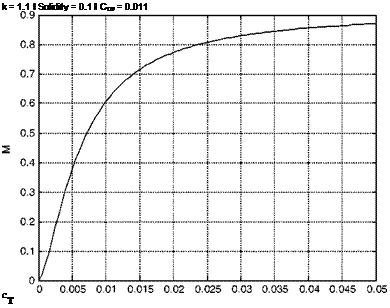
Now for a given rotor blade the drag coefficient, and hence the profile power, may be expected not to vary greatly with the level of thrust, provided the blades do not stall nor experience high-compressibility drag rise. Equation 2.19 shows therefore that the value of M for a given rotor will generally increase as Ct increases (this is illustrated in Figure 2.2). This feature means that care is needed in using the figure of merit for comparative purposes. A designer may have scope for producing a high value of M by selecting a low blade area such that the blades operate at high lift coefficient approaching the stall, but they need to be sure that the blade area is sufficient for conditions away from hover, such as in high-speed manoeuvre. Again, a comparison of different blade designs – section shape, planform, twist, and so on – for a given application must be made at constant thrust coefficient.
A good figure of merit is around 0.75, the profile drag accounting for about one-quarter of total rotor power. We may note that for the helicopter as a whole, some power is also required to drive the tail rotor, to overcome transmission losses and to drive auxiliary components: as a result the induced power in hover amounts to 60-65% of the total power absorbed.


