LIFT OF SWEPT WINGS
When analyzing swept wings, the angle of attack of swept wing is defined as that in the plane of symmetry, the dynamic pressure in the direction of flow or flight, and the wing span the straight distance between the wing tips or lateral edges.
Figure 4. Lift-curve slope of straight wings when sideslipp ing at an angle of yaw.
(4) The lift of straight wings when sideslipping:
a) Moller, Rectangular, Luft’forschung 1941 p 243.
b) Doetsch, Rect & Elliptical, Ybk D Lufo 1940, 1-62.
c) Schlichting, Survey, Yearbk D Lufo 1940 p 1-113.
d) Purser, Various Wing Shapes, NACA TN 2445, (1951).
e) Hansen, 5 Elliptical, Yearbk D. Lufo 1942 p 1-160.
0 Goodson, Swept Sideslipping, NACA RM L1955 L20.
(5) Chordwise distributions measured on swept wings:
a) Thiel, Straight/Swept, ZWB UM 1293, NACA TM 1126.
b) See results in references (2,a) (7,a) (7,b) (12,e).
c) Whitcomb, Isobares, NACA RM L1950K27, K28, L07.
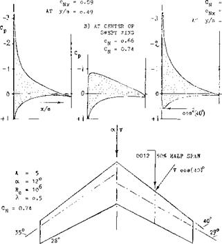
distribution across the straight wing is roughly elliptical, the swept-back shape exhibits a deficiency in the center and overloaded outboard parts. On the other hand, the swept-forward wing shows comparatively small loads on the forward ends and an overloaded center. These load distributions have severe consequences in regard to stalling, maximum lift, longitudinal stability (pitching up) and control (downwash and wake at the horizontal tail); and in the swept-back shape also upon roll stability and control. All of these aspects are discussed later in th. s and Chapter XVI.
A) IN CENTER OP STRAIGHT V/ING
|
cN = o.80 C) AT 509» OP HALF CN = °-8? CN –
|
Figure 5. Chord wise pressure distributions tested (5, a) at several stations along the span of a straight and a swept wing.
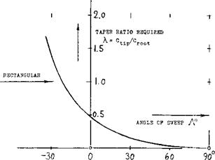
TAPER RATIO. As pointed out above, and as seen in figure 6, the load distribution of swept wings can be considerably different from elliptical. To make these distributions nearly elliptical, theory (6,f) indicates the required taper ratios as plotted in figure 7. For a wing swept back to Л = 30°, for example, a taper ratio of X == 0.15 would thus be needed. The idea is to give the wing more [129]
|
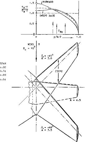
Figure 6. Load distribution across the span of three different wings (7,a) showing the variation as a function of the angle of sweep. |
lift in the center and to reduce the loads on the wing tips. Necessarily this would mean higher lift coefficients (as distinct from loads (L/q) per ft or meter of span) on the wing tips. In a practical wing design, the result would be a very undesirable type of tip stalling. Aside from such considerations, references (8,a) indicates that (in the combination of a 45° swept wing with a fuselage) a taper ratio of 1.0 (rectangular panels) is as efficient in producing lift as 0.6 (tapered); and either one of these is better than a taper ratio of 0.3. Another method of making the lift distribution nearly elliptical is indicated in (1). The center of the wing might be given an increased angle of attack д or = A/6.
(7) Spanwise load distribution, experimental:
a) Jacobs, 4 Wings, ZWB UM 2052 NACA TM 1164.
b) Loving, Including Fuselage, NACA RM L54B09.
c) Mendelsohn, Forward & Back, NACA TN 1351; also same model with flaps, Letko TN 1352.
(8) Experimental characteristics of swept wings:
a) King, Wing-Fuselage Combinations, NACA TN 3867.
b) German ZWB Reports FB 1411 and 1458.
c) Tolhurst, Vortex Sheet 63° Swept, NACA TN 3175.
d) Cahill, Tapered A = 4, NACA RM L9J20/L50F16.
e) Kuchemann, 45° Swept Wings, ARC RM 2882.
f) Hopkins, With —40°/+45° Sweep, NACA TN 2284.
g) Goodman, Various Wings in NACA TN 1835 & 1924.
|
|
|
Figure 7. Taper ratios, theoretically required to make or to keep the lift distribution of swept wings as “good” as elliptical (6,f). |
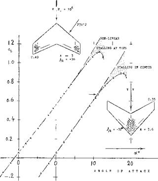
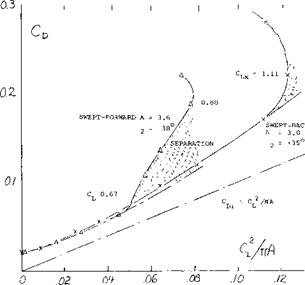
FORWARD SWEEP. If there are any over-all merits of swept-forward wings they are found in the “never” stalling wing tips (discussed in Chapter XVI). For finding lift the simple theory expects the cosine principle to apply in the same manner as in swept-back wings. As shown in figure 6, their spanwise load distribution is different, however. Lift and drag characteristics of a swept-forward, in comparison to a swept-back wing (having roughly the same aspect ratio), are presented in figure 8. Flow separation in the center of the swept-forward wing begins around oc = 10°, where CL ~ 0.7. This is particularly evident in part (b) of figure 8. Loss of lift and growth of drag are considerable. Stalling in the swept-back wing seems to be “creeping” between C L =0.7 and 1.05. As far as the magnitude of lift is concerned, this does not have too much of an influence, however.
INDUCED ANGLE. As stated in Chapter III, the induced angle is a minimum for the optimum distribution of lift across the span of any straight wing. To account for the influence of sweep, there does not seem to be any simple method available. It follows, however, from what is presented in Chapter VII of “Fluid Dynamic Drag” that the increment of the induced drag corresponds to
Act L /oCL = (к/A)A (12)
where (к/A) is a function only of the taper ratio. Using the approximation as in figure 5 of Chapter III, we find for the induced angle (rather than drag):
In straight wings realistic values of K, that is for tapered wings with X between 0.4 and 1.0, may be in the order of 0.05. Equation (13) thus leads to values well below 0.1°. Considering an increment of 1% in the induced drag to be negligibly small, the possible influence of lift distribution may be disregarded (that is, in comparison to the various other uncertainties in any airplane configuration).
|
|
|
Figure 8. Lift and drag data of a swept-forward in comparison to that of a swept-back wing (9,f). |
DRAG DUE TO LIFT To determine the drag due to lift as a function of angle of attack as in the set-up in figure 2, the panels should be rotated (twisted as a whole) against the center axis of the swept wing. This is done in most airplanes, at least by some 3°, to keep fuselage and passengers on a level floor when cruising. Aerodynamic rotation is also obtained when deflecting trailing edge flaps and/or ailerons. In all wind-tunnel tests, the whole wing is pitched, however, rather than rotating the wing panels relative to the center body, a perfectly plane wing, such as a swept-back flat plate, the tips drop below the level of the center. A negative angle of dihedral thus develops. The influence of dihedral as such is comparatively small (see Chapter III). In swept wings, the lifting forces are tilted sideways, however, in addition to being tilted back by the induced angle. As found empirically (in Chapter VII of “Fluid Dynamic Drag”) the drag due to lift increases accordingly, corresponding to
dCD/dCf ~ 1 /cos. A (14)
It is believed that this increment (of induced and/or separation drag) is due to viscosity (boundary layer accumulation at the ends of the swept-back wing panels).
|
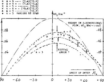
Figure 9. Lift-curve slopes of wings having aspect ratios between 3 and 6, as a function of their angle of sweep. |
LIFT ANGLE. The angle-due-to-lift involved in equation
(14) would lead to the following modification of the “lift angle” presented at length in Chapter III thus, if all the drag in equation 14 were considered to be induced
dcq/dcL dCD/dCL= 20/AcosA 05)
and the total angle of wings with larger aspect ratio
doc °/dCL = (10/cos Л ) + [20/(A cosЛ )] (16)
Writing this equation in the form of
dCL /doC = cos-Л/[10 + (20/A)] (17)
a qualified confirmation is obtained by the results in figure 9. Assuming, however, that the induced drag of a swept wing be the same as that of a straight planform, the angle of attack of wings with not too small aspect ratios should be expected to be
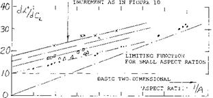
(doc °/dCL ) = (10/cos – A*) + (20/A) (18)
For А^= 25°, figure 11 confirms this function sufficiently well. However, the lift angles for Л = 50° are definitely higher than expected by equation 18. For the Л = 50° wing using equation (16) the right order of magnitude of dot°/dC_ is obtained. The mechanism of highly swept wings is thus believed to be different than that expected by the simple swept theory. The accumulation of boundary layer mentioned above can also be expected to be larger in higher aspect ratios (in long wing panels), while in smaller aspect ratios the distinction between swept and straight wings generally disappears; thus the boundary layer effects of swept wings must be considered.
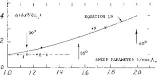
The lift angle increment believed to be attributed to viscosity based on experimental results is given in figure 10. This increment appears to be a function of l/cos2A,
(10) Influence of fuselage on lift of swept wings:
a) Pressure & Load Distributions, (7,b, c)(9,b).
b) West, Fuselage Location, NACA RM L1953B02 (21,e).
c) Johnson, Wing With Bodies, NACA RM L195 3J09a.
d) Schlichting, Influence, ARC RM 2582.
11) Diederich (NACA), analysis of lift f(A) and f(A):
a) Correlation on the Basis of “F”, TN 2335.
b) Spanwise Lift Distribution (Flaps), TN 2751.
(12) Wings with negative (forward) angles of sweep:
a) Hopkins, Half Wings A = 3 to 7, NACA TN 2284.
b) German ZWB Rpts FB 1411 and 1458 (1940)(8,b).
c) Junkers Ju-287, Jane’s A W Aircraft 1945/45; or Aircraft Fighting Powers, Vol 7 Harborough 1946.
d) McCormack, Stalling Swept-Forward, NACA TN 1797.
e) Whitcomb, at M = 0.6, NACA RM L1950K28 (5,d).
0 Purser, A = 3 With -45/+600 Sweep, NACA (9,e).
Thus, one way of describing the lift of highly swept wings is to add a constant increment in figure 11, which might be of the form
A(doc° IdCL ) = 1/cos2-A (19)
For -A*. = 50° the corresponding line in the graph averages the experimental points.
EXPERIMENTAL RESULTS:
|
+ VARIOUS (5,c) (11,a) (12b, d)(12,b) x WINGS WITH 60° OF SWEEP (9,a) & WINGS WITH NEGATIVE SWEEP (12,b) о HALF WING WALL MODELS (12,a) A " 4 to 6
Figure 10. Increment of the lift angle caused by viscosity, as a function of the sweep parameter (l/cosA+. ). |
wing, and at x/c^24% over most of the outboard two – thirds of the half span. In the words of (25,b) the “pressure peak line” determines the effective angle of sweep. The effective reduction of positive angles of sweep as in equations (20) and (35) is thus explained. To approximate the neutral angle as in figure 9 the line connecting the lh chord point of the root chord with the % point at the lateral wing edges is suggested to indicate the effective angle of sweep. This angle is illustrated in figure 5, where it happens to be 29° instead of 35°. In tapered wings, the difference as against the usual % chord definition is then found to correspond to
(Д-Л) = — (1/A)tan(l/1 + X ) (20)
For an assumed taper ratio A =0.5, the differential is Д-Л = —34°/A. For example, for A = 5, a A A^7° is indicated, which is not too much in comparison to what is evident in figure 9. We will identify the effective angle of sweep by the subscript (+), thus A + =A-A + A c/4 , and use this angle in equations (16) and (17). Thus equation 17 becomes
(dor° /dQ_ ) = (10/cosA,.) + (20/A cos 7+) (21)
|
x FOR J = 50° □ FOR, A+ = 40° Л FOR J+ = 25° о STRAIGHT WINGS
0 0,2 0,4 0.Q 0,8 Figure 11. The lift angle of swept wings (with larger aspect ratios) as a function of (1/A). |
NEUTRAL ANGLE OF SWEEP. It is seen in figure 9 that the “zero” angle of sweep (where dCL /doc is highest) is shifted to – A/4 around +5° for A = 6. A corresponding shift by 5° is observed in Chapter VII of “Fluid Dynamic Drag” for the minimum of dC0 /dc£ . This is an empirical fact. It can be said, however, that there is no cross flow at the center line of swept wings. The cosine principle applies in the outboard parts, say in the outboard two-thirds of the half spans. Shown for example in (26,c) and (26 Jh) the aerodynamic center of lift of the sections is around x/c = 40% in the center of a typical swept-back
INFLUENCE OF FUSELAGE. A convenient wind-tunnel technique is to attach half of the wing span (a half wing) to a wall or an end plate. Results are as follows:
a) As stated above, the lift-curve slope is reduced because of the boundary layer present and/or developing along the “wall”.
b) The flow pattern past the roots of swept-forward wings (as sketched in figure 8) seems to be improved, at least in comparison to that of swept-back wings, where the roots are rather disturbed.
Since fuselages do have a boundary layer, “wall” interference could reduce the lift-curve slope of swept-back wings. However, lift is generally increased and the “lift angle” decreased when testing in combination with a fuselage body. Shown in (7,c) the lift (in units of force per unit of span) carried by the fuselage is roughly the same as in the inboard Vi of the half-span of the 45° swept-back wing. This means that the dip of load as in figure 6, for example, is not present. In fact, there is possibly a pair of peaks induced by the fuselage on the wing roots (by way of the two-alpha principle, as explained in Chapter III). Thus, the lift on and by the fuselage is larger than it would be in the center of the wing when tested alone. As a consequence, the total lift of the wing-body configuration is increased over that as indicated in the various illustrations.
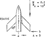
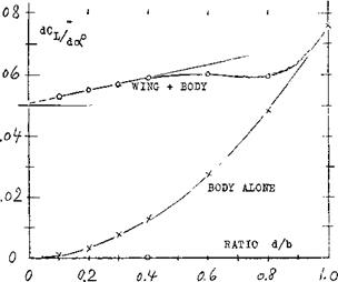
 The influence of the body upon lift depends upon its size. As a function of the diameter ratio d/b, figure 12 shows how the combined lift L w& varies, resulting approximately in
LWB/Lw = 1 + 0.5 (d/b) (22)
valid up to d/b = 0.4. References such as (9,b) confirm that lift is increased by the presence of a body in midwing position. As an interesting byproduct, the maximum lift coefficient (based on original wing area) is increased from C Lx = 0.9 to 1.8 when adding a fuselage with d/b = 0.4. Considering the high lift at d/b = 1, that is of the body alone, it should be realized that there would be in that graph a body with a length equal to 5 or 7 times the span of the original wing.
0
STRAIGHT RECTANGULAR, CHAPTER III
H STRAIGHT TAPERED, CHAPTER III
Я VARIOUS SWEPT WINGS. AS EVALUATED IN (11,a)
a SWEPT RECTANGULAR PANELS (9,f)
V SWEPT-BACK TAPERED WINGS (9,f)
+ RECTANGULAR SWEPT PANELS. AS FIGURE 9 Д SEVERAL SWEPT-BACK 60° WINGS AS IN(7,a)(9,f) x SWEPT-FORWARD TAPERED WINGS AS IN (8,b)(9.f) + SWEPT-FORWARD RECTANGULAR PANELS, AS IN (9,f)
1 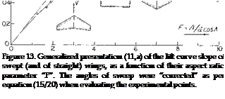 PLUS/MINUS SWEPT, AS FIGURE 9
|
|
|
Figure 12. The lift-curve slope (up to C L =0.8) of wing-body combinations (10,c) as a function of the diameter/span ratio. |
ASPECT RATIO. The function such as in equation (21) is no longer correct within the range of aspect ratios, say below 4. A very useful method describing the lift-curve slope of swept wings down to aspect ratios below unity is presented in (1 l, a). Defining the modified aspect ratio
F = A/а cosЛ* (23)
the lift-curve slope of swept and/or straight wings is indicated by the ratio
(dCL /doc )/(CL<fcCosAr) = F/(2 + vF + 4) (24)
For conventional airfoil sections we can assume a = 0.9 and CLcC = (dCL/dod°2 ) = 0.1. Available experimental results have been evaluated on this basis and plotted in figure 13 in the form of
(dCL /doc )/(0.1 cosy+ ) = F/(2 Wf2 +4) (25)
Aspect ratios between zero and infinity are covered by this equation. The assumptions made in (11,a) permit presentation of a broad field of aspect ratios and sweep angles in one graph. Below F = 0.8 a limiting linear function is found. Combining equations (23) and (25) we obtain
dCL /d<x° = A/36 (26)
for “A” well below unity and for not too large angles of sweep. This equation is essentially the same function as that in the chapter dealing with “low-aspect-ratio wings”. The interesting result is that the influence of the angle of sweep simply disappears.
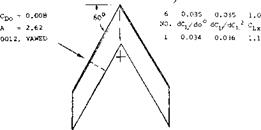
“CRANKED ” WINGS – M & W. Wings with a planform shape of an “M” or “W” are also called “cranked” wings (13,b). The idea for the use of these shapes was to delay or eliminate the pitch up moment encountered with swept wings, see Chapter XVI, and thus allow the use of higher values of sweep. Also, the same degree of sweep can be obtained with “M” or “W” without the need of extending the tips so far back. This was thought to have structural and aero-elastic advantages.
![]()
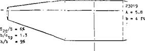
 Tests did show an advantage with the pitch up moment at angle near stall (13,f). The performance of the “M” and “W” planform wings was expected to be below that of the plane sweptback wing because of poor flow at the bends of the wing. The data of (12,b) does not confirm this as shown on figure 14. In fact, the performance of the “W” wing is slightly better than the equivalent 60° swept back wing, except near maximum lift. Although there appear to be advantages in the use of “M” or “W” wings, the practical design and construction problems have apparently eliminated their use.
|
R = Ю6 c
|
|
— Ъ – 4.3 ft Figure 14. Characteristics of a 60° “cranked” or “W” wing in comparison to those of a plain swept wing (29,f). |
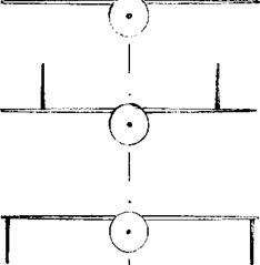
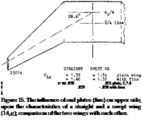
END PLATES. As presented in Chapter III any addition of end plates increases the lift-curve slope of straight wings. The maximum of (L/D) of swept wings is reduced, however, as shown in (14,g). The flow over the wing tips (prone to stall) is evidently made more difficult by the presence of end plates, after exceeding small lift coefficients. Some drag and lift results are presented in figure 15. At CL = 0.6, total drag is somewhat reduced when adding the upper-surface fins. For a height ratio of h/b = 9% the reduction could be expected (see Chapter VII of “Fluid Dynamic Drag”) to be in the order of Л C0 = —.003, which is 10% of the total at CD = 0.6. Interference (not only in the swept, but in the straight wing as well) increases the viscous drag more than 30%. The maximum lift of either the straight or swept wings is only slightly effected by the use of end plates on the upper side. In (14,g) the end plates (on upper side) were also kanted, by 7.5° in and out, respectively. When kanted-in (toed-out, we would say) the flow pattern within the corner between wing surface and plates was slightly improved. When kant – ing outward, drag was increased. It thus shows that the weak flow over the wing tips cannot be improved appreciably.
VERTICAL FINS. Vertical fins on top and/or below the wing can be used in tailless airplanes (using sweep-back) and will provide directional stability, Chapter XII. In the configuration as in figure 16, there is a small increase of
15-11
|
|
|
|
|
|
|
|
|
|
|
|
|
|
![]()
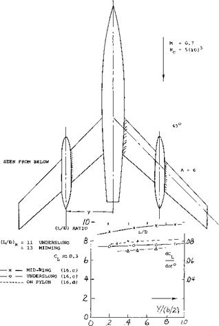
ENGINE NACELLES. The pylons (struts) supporting jet engines below the wing (15) are in aerodynamic respect similar to end plates, moved inboard (say to Й half span). They might thus be expected somewhat to increase the lift-curve slope. Even engines without pylons, but underslung (16), have an effect of this kind. As shown in figure 17, the lift-curve slope increases slightly when moving the nacelles toward the wing tips. The lift/drag ratio is, of course, higher with the nacelles in midwing position then when located inboard (less frontal area). Also, the maximum of that ratio (at CL^0.3) increases noticeably when moving the nacelles outboard.
(15) NACA, external stores on Douglas D-558-II:
a) Silvers, Various Shapes Subsonic, RM L.1955D11.
b) Kelly, In 2 Spanwise Locations, RM L1955107.
c) Smith, Characteristics at M = 2, RM L1954F02.
(16) Engine nacelles on swept wings:
a) Pressure Distribution, ZWB UM 3176, NACA TM 1226.
b) Boltz, Pressures and Forces, NACA RM A1950E09.
c) Silvers, Spanwise Position, NACA RM ІЛ953НГ7.
d) Pearson, At Transonic Speeds, NACA RM L1957G17.
e) Hieser, Sweep and Fences, NACA TN 1709.
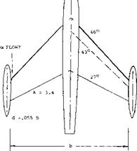
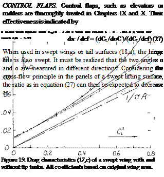
TIP TANKS – SWEPT WINGS. Wing tip tanks are used on swept wings for the same reasons as were discussed for straight wings in Chapter III. Also, the general flow and interference characteristics encountered are similar. The relative performance (17,c) of a swept wing with and without tip tanks is shown on figures 18 and 19 and includes data with end plates of a comparative height. As shown on figure 18, the lift curve slope increases from.054 for the wing with square tips to .063 with tip tanks. This increase is even larger than for the wing with end plates of a similar height. The data plotted on figure 18 is all referred to coefficients based on the original wing area. However, if the lift angle and slope are adjusted for the change in area and aspect ratio, the end plate effect of tip tanks agrees with corresponding data for end plates.
In comparing the drag as measured in (17,c) the use of tip tanks does not show any improvement over the original sharp tip wing, figure 18. This result cannot be generalized, however. In the configuration as tested, there was a
|
Figure 18. Lift characteristics (17,c) of a swept wing with and without tip tanks. All coefficients based on original wing area. |
|
/ x* / |
 |
 |
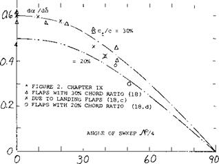
doc /dd — cos A (28)
The scattering results in figure 20 seem to confirm this reduction. An inspection of the effectiveness of outboard ailerons (19) shows that their roll moments reduce at a rate even stronger than in proportion to cos A. The same deterioration is also found in swept-forward wings (19,a).
(17) c) Salter and Jones (NPL), Swept Wing with End Plates in CAT, ARC Current Paper 196(1954).
d) Hartlet, Tip-Tank analysis, ARC CP 147.
e) RAE, On Swept-Back Wing, ARC RM 2951.
f) Weber, Analysis Wing & Body, ARC RM 2889.
g) NACA Tunnel Tests, RM A5F02, A5G02, L9J04.
(18) Effectiveness of Swept trailing-edge flaps:
a) Dods, Horizontal Tails, NACA TN 3497.
b) Harper, Tail Surfaces, NACA TN 2495.
c) Small Chord Ratios, NACA TN 2169 and RM L8H20.
d) Young, Wing Flaps, ARC RM 2622.
Ц9) Effectiveness of ailerons on swept wings:
a) Luoma, Ailerons on Wings, NACA L1947115.
b) Bennett, Roll Moments Swept Wings, NACA TN 1278.
|
|
|
Figure 20. Lifting effectiveness of full-span wing – and/or control – surface flaps, as a function of their angle of sweep. |
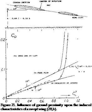
GROUND EFFECT: Ground effect, that is the influence of ground proximity when taking off or landing, upon the lift of straight wings, is presented in Chapter XX In the case of swept wings, it can be visualized that the tips of a wing with 60 sweep, for example, would eventually touch the ground, while the apex is still high in the air. Lift and drag of a 40° swept wing are plotted in figure 21. Around zero lift the induced angle ratio (for CL = constant) is approximately (dod L 3 /doc u ^ )
= 0.54 evaluated from lift
= 0.63 corresponding to drag.
These values are smaller than those in figure 28 of Chapter III, for h/b = 0.18, measured to % of the mean chord. As discussed in that chapter, reasonable agreement can be found when defining the ground distance to the % point of the mean chord. This would also straighten out the CL (od ) function. However, above CL = 0.7 a deficiency of lift is seen to exist in the presence of the ground. The cause is stated in (20,b) to be “intermittent stalling” along the trailing edges (outboard). — The ground effect is, of course, of particular interest when landing an airplane; and that is usually done with the wing flaps extended. Deflected flaps are aerodynamically equivalent to an increase of the angle of attack. As found in (20,b) the same reduction of the induced angle is obtained as in figure 21. Stalling begins, however, at the same lift coefficient as without flaps. Subsequently, the drag due to lift increases progressively with the lift coefficient. The flapped center portion of the wing eventually stalls, resulting in a maximum lift coefficient reduced from 1.41 (in free flow) to 1.24 (near the ground).
v20) Influence of ground on lifting swept wings:
a) Thomas, Theory/Experiment, Ybk WGL 1958 p 53.
b) Furlong, Experimental, NACA TN 2487 or Rpt 1218.
c) Hafer, Z FlugWissenschaften 1958 p 20.
d) Wyatt, On “M” Wing, ARC C’Paper 541.
e) 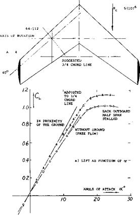
 Wood, Effect on “Swift Model, ARC C’Paper 458.


