NUMERICAL EXAMPLE—STEP RESPONSE
For the same airplane and flight conditions as in the previous example, the response to a step-function input in the elevator angle was computed, using (5.13,19) mechanized for a 10-volt analog computer. As an aid to readers unfamiliar with analog computation, the details of this one example are set out rather fully. The other examples that follow later were computed in essentially the same way, but the details of scaling and circuits are omitted. With the same assumptions as made previously the differential equations with numerical coefficients are:
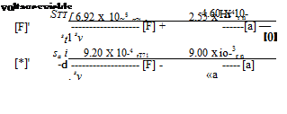
Df = -6.92 x lO-5 A F + 2.55 x 10~4 Aoc – 4.60 x 10~4 А в
Doc = -9.20 X 10⁻⁴ AF – 9.00 X 10~3 Aoc + q – 4.42 X 10"4 Me
Dq = 2.03 X 10⁻⁶ A V – 3.62 x 10~4 Aoc – 1.43 X I0~2q – 3.77 X 10~4 Me
D6 = 4 (10.2,18)
To mechanize them for analog computation we make the following transformation of variables:
[V]=srAf; [«) = *. Да; [q] = sqq; [0] = se Д0 (10.2,19)
where the quantities in square brackets, [F] etc., denote machine voltages, and sr etc. are scale factors. Time scaling is by the law
T = stt
where t is laboratory clock time, or macsecs (for computing machine seconds), and t is the nondimensional time variable of the differential equations. To relate the computer results to real flight time t we use t
r = st~, t* = .0105 see (10.2,20)
On recalling that D in (10.2,18) represents d/dt, and defining [ ]’ = (ri/rir)[ ], the transformation of the equations into differential equations for the
 + -[?] -4.42 x 1<Г*Дд, M’ = (2-°3 X 10~6 [F] – 3-62..X 10 4 [a]
st l SV sx
![]()
 |
И – 3.77 x 10~4
[0]’ = M
StSQ
Note that we have chosen for convenience to give the control angles as ASe, rather than [d]/ss, since Ade not [6] is to be specified. The scale factors used were as follows:
sr — 10 v/unit sx = 10 v/radian
sq = 1000 v/unit se = 10 v/radian
Since the response shortly after t = 0 is governed mainly by the short-period mode, and the long-term response by the phugoid mode, a single time scale is not appropriate for both. Hence two time scales were used:
To show long-term response: st = 10~3
To show initial response: st = 10-2
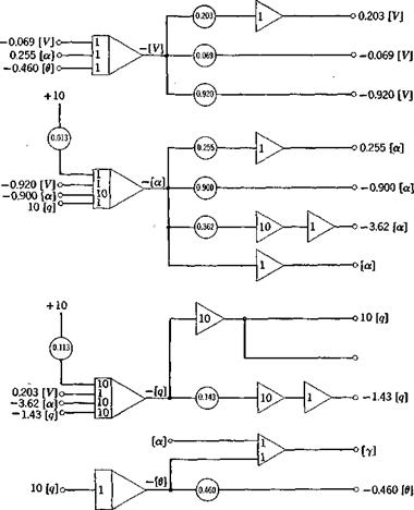
The analog circuit for st = 10“3 and Аёе = —.03 rad is shown in Fig. 10.4, using conventional symbols for integrators, summers, etc.
When st = 10~3, the time relation, from (10.2,20) is
f*
t = – T= 10.5r
and hence the process proceeds about 10 times faster on the computer than in flight. When st = 10 ~2, the process proceeds at nearly real flight time. The results for F, a, and у are shown for both time scales on Figs. 10.5 and
|
Fig. 10.4 Analog circuit diagram for response to elevator step. Д<5е = —.03 rad, st = 10~3. |
10.6. These curves were recorded by a conventional x — у plotter; the time base was generated on the computer by integrating a constant.
Figure 10.5 shows that a increases rapidly and quickly damps out to its asymptotic value. V and y, however, make a slow, weakly damped approach to their final values, the initial overshoot being very large for both. If the reason for moving the elevator were to change to a new steady state, the maneuver has not been a very effective one! After 500 sec the oscillations in V and у have still not disappeared. The behavior near t = 0 is shown more clearly on Fig. 10.6; the rapid rise in a is dominated by the short-period mode. It is only after a has changed that the associated increase in lift can
|
|
|
Fig. 10.5 Response to elevator (Д8e = —.03 rad). Jet transport cruising at high altitude. |
act to curve the flight path (via A. L = mVy); thus the increase in у lags that in a. At the same time the increased drag due to Да, and the “downhill” component of the weight combine to produce a reduction in speed, which lags still farther behind. The response in у is not in fact very rapid. It takes about 10 sec to increase у by about 10° with this elevator deflection. In this time the vehicle has traveled 7330 ft.


