Rotor in Vertical Flight: Momentum Theory and Wake Analysis
We begin examining rotor aerodynamics by building models based on momentum transfer – see Glauert [1]. This allows the essential performance of the rotor to be assessed. The most straightforward flight condition is hover, which provides the first part.
2.1 Momentum Theory for Hover
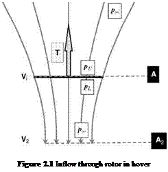
The simplest method that describes the lifting rotor is actuator disc theory. It is based on achieving a lifting force by generating a change of momentum. It assumes the existence of a streamtube which is an axially symmetric surface passing through the rotor disc perimeter which isolates the flow though the rotor. The air is assumed to be incompressible and therefore the flow past any cross-section of the streamtube is constant (Figure 2.1). This also means that because the flow is one dimensional, the flow must remain in the same direction, which for most flight conditions is appropriate. However, this does give rise to a failing of the theoretical model under certain flight conditions.
The flow enters the streamtube, is accelerated through the rotor disc and then is exhausted from the bottom of the streamtube. Far upstream of the disc, the vertical flow velocity must tend to zero making the streamtube cross-section infinite in size. However, the streamtube establishes itself and passes through the rotor disc perimeter.
The additional velocity of V as it passes through the rotor is known as the induced velocity. It finally forms the wake with a velocity increase of V2.
The rotor thrust force, T, can be evaluated by considering the momentum increase. The continuity of the flow through the streamtube allows the following:
![]() pA • Vi = pA2 • V2
pA • Vi = pA2 • V2
Basic Helicopter Aerodynamics, Third Edition. John Seddon and Simon Newman. © 2011 John Wiley & Sons, Ltd. Published 2011 by John Wiley & Sons, Ltd.

The rate of change of momentum gives the rotor thrust as:
T = pAVi • V2 (2.2)
Every second a packet of fluid enters the streamtube with zero vertical velocity. In that same second, an equal packet of fluid leaves the streamtube with a vertical velocity ofV2. Hence, in every second there is a momentum generation given by (2.2).
Actuator disc theory also uses the fact that the thrust can also be expressed in terms of the difference of air pressure on both sides of the rotor disc. In order to generate a thrust, there has to be a pressure difference, which is discontinuous since the rotor disc has zero thickness. However, the airflow through the rotor is continuous and forms part of the theoretical premise of the actuator disc.
We therefore have the following:
T = A(pl-pu) (2.3)
The final consideration is the application of Bernoulli’s equation. This equation can be applied to the flow above or below the rotor disc, but not through it. Above the rotor we have:
while below the rotor:
![]() 1 , 1 , pl + 2 PVi = P1 + 2 PV2
1 , 1 , pl + 2 PVi = P1 + 2 PV2
Subtracting these gives:
Assembling (2.2), (2.3) and (2.6) gives:
V2 = 2| (2.7)
In other words, the induced velocity is doubled as the air forms the wake far downstream of the rotor.
 |
||
Combining (2.2) and (2.7) gives the following result:
The second expression shows that the induced velocity is dependant explicitly on the disc loading T/A.
Equation 2.8 provides the link between disc loading and induced velocity. At first sight, all this would seem to indicate is that the higher the disc loading, the greater the downdraught from the rotor. Correct, but not the real punchline. The thrust force is working on a medium passing through it at the induced velocity, V). Therefore the rotor is expending power (product of force and velocity) given by:
![]() Pi = T • Vi
Pi = T • Vi
This power is given a suffix of ‘i’ consistent with the induced velocity. This is because this power is termed the induced power and is a result of generating the thrust force. If we now compare various rotors, it is apparent that the higher the disc loading, the higher the induced power. As will be shown later, the induced power forms the majority of the power consumed in hover, which is itself a high power-consuming flight regime. The disc loading is therefore one of the first items to be considered when designing a rotor system. Apart from the maximum all-up weight of the helicopter, the main rotor size is almost the first decision to be made.


