The fuselage
5.5 Before we proceed to discuss problems of mutual interference between the various organs of the classical type of aircraft, we consider first briefly some problems of the aerodynamics of the fuselage.
The main purpose of the fuselage is to provide volume. This implies that the flow past it is primarily a displacement flow. If the fuselage carries also lift forces and moments (apart from carrying lift across from one wing half to the other), then these may be regarded, in principle, as unnecessary, unintentional, or even detrimental. What is wanted ideally can be explained in a nutshell by the hypothetical case where the volume is provided (economically, in terms of surface area) by a sphere and the lift by an unswept wing of infinite aspect ratio, i. e. by a line vortex through the middle of the sphere, as treated by J Lennertz (1927). The flow past the sphere induces no upwash along the wing and so it may be argued that the addition of this fuselage does not affect the lift. But there is a streamwise velocity increment and, taking this into account and working out the load distribution over the wing-body combination, F Vandrey (1937) confirmed that the overall lift is the same as that of the wing alone, so that volume is provided without any change of lift: lift is carried across the sphere at 3/4 of the initial value, but this is compensated by an increase in lift on the wing outside the sphere. If, in another hypothetical example, the fuselage is assumed to be an infinitely long circular cylinder, then Lennertz found that not only the overall lift remains the same but also its spanwise distribution across the fuselage. These cases conform to Cayley’s principle of providing volume and lift independently. Unfortunately, there are some, often quite complex, interference effects in reality and we shall see below that these simple and attractive arguments are rather misleading and do not apply to real wings.
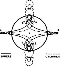
Consider first the essential displacement flow past a fuselage alone and some of the fundamental features that such flows must have. Fig. 5.29 illustrates
what must happen when a sphere (E Riecke (1888), full lines) or a circular cylinder (W В Morton (1913), dashed lines) moves from right to left through (inviscid, incompressible) still air past an observer at rest, the shape of the body being shown at the instant when it passes the observer (see also В Thwai – tes (1960), Section VII.3). We follow the motion of air particles from their
|
Fig. 5.29 Particle paths in the uniform motion of a sphere, or a circular cylinder, through fluid otherwise at rest |
initial positions (A) when the body starts at infinity on the righthand side to their final positions (B) when the body has arrived at infinity on the left – hand side. A particle will first be displaced forwards and sideways, to allow for the passage of the body, and later it will be drawn in behind the body when it has passed. The innermost curves in Fig. 5.29 are the paths of particles which move from infinity to infinity and slide along the body. The other curves describe particles situated away from the axis of symmetry. These paths explain clearly why, in such a displacement flow, the relative velocity between the air and the body is higher at the sides of the body than the speed of the body: air and body move in opposite directions while the body passes by. These particle paths also show clearly the essential difference between twodimensional and threedimensional flows: a twodimensional flow causes a much greater eonmotion and disturbance in the air than a threedimensional body, since the air can escape only to the two sides rather than in all directions.
The same flows as in Fig. 5.29 appear to be steady to an observer placed in the body. Paths of air particles are then identical with streamlines, and we arrive at the familiar streamline patterns which can be found in many textbooks. Note that the book by 0 Tietjens (1960) stands out for the excellence of the many accurate streamline patterns shown.
We have already seen in Section 2.2, in connection with Fig. 2.1, how such displacement flows can be calculated by the method of singularities, souraes and sinks being the fundamental flow elements. Distributions of sources and sinks along the axis can be used to calculate the inviscid flow past bodies of revolution, and there are also some alternative methods (see e. g. В Thwai- tes (1960), Chapter IX). In the early days, many investigations were directed towards applications to airships (see e. g. G Fuhrmann (1912), Th von Karman
(1927) ), where it is necessary to deal also with bodies which are inclined to the mainstream. It then turns out that the representation by singularities on the axis has serious shortcomings, and so I Lotz (1931) proposed to put the singularities on the surface of the body. In this approach, source rings or vortex rings may be used in the symmetrical case (see D Ktichemann (1940)), and various practical methods of great accuracy have been developed, among others by F Riegels & M Brandt (1944), F Vandrey (1951), and L Landweber (1951). The panel methods by J L Hess & A M 0 Smith (1967), A Roberts & К Rundle (1972), and M J Langley (1973) are probably the most economical and accurate methods of this kind available at present. Approximate methods have also been developed, and so there are linearised theories for thin bodies (of the kind explained in Sections 2.2 and 4.3) and also slender-body theories for shapes with small surface slopes (of the kind explained in Section 4.3; see also Sections 6.6 and 6.8). Some of these theories can also be applied at transonic and supersonic speeds (see e. g. M M Munk (1934), G N Ward (1949) and (1955), and D J Jones & J C South Jr (1975)). We recall here that the assumptions of slender-body theory imply that the lift at any cross-section of the body differs from zero only where the slope of the surface changes along the body.
Thus an inclined body of revolution with a cylindrical part in the middle carries a lift force only along the curved nose part and along the curved rear end. For a closed body, the overall lift forces over the nose, or forebody, and over the rear end, or afterbody, are equal and opposite and thus the body experiences only a moment, in this model of the flow. Despite the crude model, this result is still the main feature in practice, except for viscous effects.
LIVE GRAPH
Click here to view
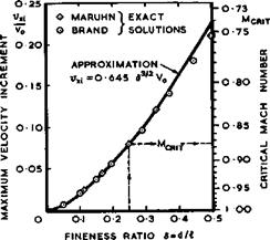
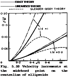
The accuracy of the linearised and slender-body theories can be judged from the results for non-lifting ellipsoids (with axes t, d, and A) in Fig. 5.30, by comparison with exact solutions for inviscid incompressible flow by К Ma – ruhn (1941). Exact solutions by Maruhn and by M Brandt (1944) have also been used in Fig. 5.31 to show that the maximum velocity increment on ellipsoids of revolution in incompressible flow can be approximated by
LIVE GRAPH
Click here to view
The Aerodynamic Design of Aircraft
|
Fig. 5.31 Maximum velocities and critical Mach numbers of ellipsoids of revolution |
up to values of the fineness ratio d/& of about 0.3* This can be used to derive a simple rule for the velocity rise with Mach number (see D Ktichemann (1951)): according to the Prandtl-Glauert analogy, the velocity increment vx in compressible flow is 1/6^ times the velocity increment vxa in incompressible flow on an analogous body, obtained by reducing the lateral dimensions of the original body in the ratio 3:1. Thus vxa ■ $3/2v ^ ^ (5,24),
and finally xl
|
|
This rule is quite a good guide for bodies of revolution. It shows that the velocity increases much more slowly with Mach number on threedimensional bodies than the Prandtl-Glauert rule (vx/vxi “ 1/8) indicates for twodimensional bodies. Thus critical Mach numbers (shown on the righthand scale of Fig. 5.31) are also relatively high.
Most of the work so far has been concerned with bodies of revolution and with conventional fuselage shapes which have a distinct forebody, then a long cylindrical portion, followed by an afterbody ending in a point. Non – axisymnetric fuselage shapes in inviscid subsonic or supersonic flows can also be treated by a method devised by H Rothmann (1972) and, in particular, the behaviour of the flow near the nose of a blunt body has been investigated among others also by H Rothmann (1972) and by P G Pugh & L C Ward (1970), and that of the flow past various shapes of rearbody by G Schulz & К Wichmann
(1972) . What should be noted is that it is by no means clear that the conventional fuselage shape is best suited for practical applications within Cayley*s concepts with regard to volume utilisation and to drag and weight. Detailed proposals for unconventional fuselage shapes have been made by H Hertel (1963) and by E S Krauss (1968) and (1970), which may have advantages and approach an ideal body more closely. These shapes have not yet been worked out and exploited in practice.
Viscosity effects in the flow past fuselages are, in principle, much the same as those discussed already in Section 4.5. D F Myring (1972) has provided a method which corresponds to those developed for aerofoils where, in an iterative procedure, the boundary-layer development is calculated first in the pressure field of the inviscid flow and then recalculated, taking account of the displacement thickness. It is especially important in this case to continue the calculation into the wake. It has not yet been possible to put this powerful method fully to the test, largely because of uncertainties in the available experimental evidence. Further experimental work of a more definitive nature is needed.
Myring’s method applies to turbulent boundary layers in subcritical flow and largely supersedes the well-known method of A D Young (1939) for calculating the pressure and skin-friction drags of bodies of revolution at zero angle of incidence, in which some simplifying assumptions about the properties of the boundary layer and of the wake had to be made, which can now be calculated. If the boundary layer is laminar, quite accurate methods are available to calculate it (see e. g. N A Jaffe & A M 0 Smith (1972)), which are based on the Mangier transformation that links the boundary-layer equations to those in twodimensional flows (see К W Mangier (1946),* N Rott & L F Crabtree (1952)).
But as in many other cases, we are as yet not very sure about estimating where transition to a turbulent flow takes place and what form it takes. Studies of more complex boundary-layer flows on inclined slender bodies have been made by T Nonweiler (1955). Using general boundary-layer concepts,
J L Hess & R M James (1975) have determined shapes of axisymmetric bodies which have low drag at high Reynolds Numbers.
We have already discussed in Section 4.6 that it is in general not possible to carry out the iterative procedure for the determination of the effects of viscosity when threedimeneionat flow separations occur, mainly because we find it difficult to predict either when and where they occur or what form the separation surface takes. One step in this direction has been done by W Geissler (1972) and (1974), who calculated first the potential flow about bodies of revolution and then the development of the laminar boundary layer by an efficient finite-difference procedure. A condition of numerical stability served as a criterion for separation to occur. As it turned out, the limiting streamlines in the surface formed an envelope, as in an ordinary separation line, when the stability condition was violated, but vortex sheets which should spring from the separation lines were not taken into account. A general method to calculate the flow past bluff bodies with wide wakes has been developed by P W Bearman & J E Fackrell (1975) , using distributions of discrete vortices over the surface. For wake flows see R R Clements & D J Maull (1975).
Some possible flow patterns of separated flows over the nose of a slender body of revolution are shown in Fig. 5.32. The angle of incidence is assumed to be large enough for separation to occur somewhere. If we assume that separation starts at a singular separation point S somewhere on top of the body in the plane of symmetry, several different types of flow, involving bubbles and vortex sheets, seem to he possible at first sight and some are sketched in Fig. 5.32. We are as yet in no position to define any of these flows in detail, nor do we have any criteria to distinguish between them and to predict which of them will occur in a real flow. There is, therefore, no basis for an effective theory. What we may expect is that a flow with vortex sheets only, as in case (c) in Fig. 5.32, may occur if the body is very slender. The vortex cores, in particular, are then left behind in the flow. Such body
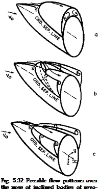
vortices are generally an undesirable feature in the aerodynamic design of classical wing-fuselage combinations.
A rough estimate of the overaVl forces and moments acting on a slender body of revolution with vortex sheets only can be obtained from the model which
 LIVE GRAPH
Click here to view
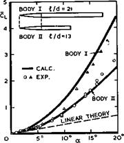
leads to (4.11) and (4.113) in Section 4.6 (see D Kiichemann (1955), where estimates of the overall drag may also be found). For the two bodies sketched in Fig. 5.33, it has been assumed that separation occurs along the cylindrical part of the body at all angles a (in this figure the lift coefficient has been referred to the base area ird^/4). This may, in fact, happen only at angles greater than 5° or 10°, but then the simple flow model seems to provide an adequate description of the overall properties of the bodies, for the time being.
The crossflow-drag concept discussed in Section 4.6 has been used by H J Allen & E W Perkins (1951) and applied to inclined bodies of revolution. At one time, it was thought that it should be possible to define a non-steady motion of a cylinder of infinite length normal to itself in a twodimensional field, which is equivalent to the threedimensional flow past an inclined body of finite length (see e. g. H R Kelly (1954)). Such an equivalence exists and may usefully be applied in the special case of a slender body in inviscid flow. But it does not seem possible to derive such an equivalence from the Navier-Stokes equations, and thus the crossflow concept becomes doubtful in viscous flows, especially if flow separations are involved.
Flow separations may also occur on the afterbody of a fuselage, especially when it is relatively short or asymmetrically upswept. It is unlikely that the flow will always remain strictly attached right up to a pointed tail, and this casts some doubt on how and where the Kutta condition should be applied on threedimensional bodies. If, on an inclined body of revolution, the flow separates upstream of the tail, the download over the afterbody is likely to differ from the upload over the forebody, and the body as a whole will then experience not only a moment but also a lift force.
Investigations with very instructive results have been carried out by W J Rainbird (1968) on right-circular cones inclined to the mainstream. Circumferential t not lengthwise t pressure gradients are the main feature of the flow, and the threedimensional boundary layer develops in a flowfield where the streamlines in the outer inviscid stream are not only curved but also converge or diverge laterally, quite unlike the conditions in the flow over infinite sheared wings. Special threedimensional effects arise on the leeside of the body where the pressure changes in such a way that continuity requires convergence of the outer streamlines in a lateral direction as well as normal to the surface, leading to a thickening of the boundary layer. It is then sometimes difficult to detect where convergence and thickening of the boundary layer ends and where separation begins. Thus the ordinary threedimensional flow separation may be a gradual and often quite steady process in the manner sketched in Fig.2.7. On slender inclined cones, the separation surfaces usually take the form of vortex sheets with rolled-up edges. The flowfield induced by these cannot yet be calculated, and thus the general iterative procedure cannot be completed.
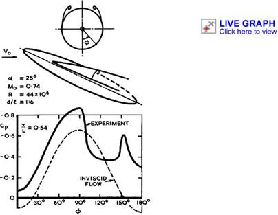
Threedimensional flow separations on more general shapes have been studied by W J Rainbird et al. (1966) and by D J Peake et al. (1972) (see also F R Grosche (1970)), and we quote here some results obtained on a prolate ellipsoid of a fineness ratio Л/d of 6:1, tested when generating lift at subsonic speeds at a relatively high Reynolds number so that the boundary layer was fully turbulent. The example in Fig. 5.34 shows a sketch of the flow, involving two primary vortex sheets on the leeside, and a circumferential pressure distribution at a chordwise station. This is quite different from the first approximation for attached inviscid flow and displays the typical additional
suction peaks induced by the rolled-up cores of the vortex sheets, in the same way as we have seen it in the case of tip vortex sheets in Fig. 4.34. We note that the threedimensional flow in a plane across the body is fundamentally different from the well-known twodimensional flow at right angles to a circular
|
Fig. 5.34 Flow pattern (schematic) and circumferential pressures on an ellipsoid. After Peake et al. (1972) |
cylinder, in inviscid or in viscous flow. This confirms that the crossflow – drag concept has no physical meaning. The results in Fig, 5,34 also demonstrate the shortcomings of the theory based on a model with plane vertical vortex sheets, leading to overall forces as shown in Fig. 5.33: this theory may give a rough estimate of the overall non-linear lift increment, but it cannot predict any details of the pressure distribution like those illustrated in Fig.
5.34. An adequate theory still remains to be developed.
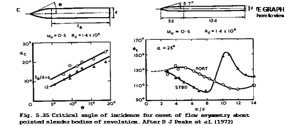
Although threedimensional flow separations on long slender bodies may often be regarded as steady, there is a strong possibility that asymmetric periodic oscillations may occur in the manner discussed in connection with Fig. 2,16, especially if the ordinary separation lines are not fixed along a sharp edge but may move about, which they can do readily when the shape of the body is rounded. These phenomena were studied in classical investigations by W J Rainbird et al. (1966) and by D J Peake et al. (1972) by testing bodies of revolution with parabolic ogive forebodies and long cylindrical afterbodies, as sketched in Figs. 5.35 and 5.36. Three distinct types of flow were detected over a range of angles of incidence on any given configuration, corresponding to attached flow, symmetric separation, and asymmetric separation. The attached-flow regime extended only to small angles of incidence (typically up to a = 3°) and the lift then increased linearly with a and also with Mach number and seminose angle 6 • The onset of flow asymmetry is shown in Fig.
5.35, as it depends on the angle of incidence and on the seminose angle.
![]()
The Design of Classical and Swept Aircraft
Fig. 5.36 Asymmetric primary separation angles on pointed slender body of revolution. After D J Peake et at.
(1972)
Fig. 5.36 illustrates how the primary separation lines move about on the port and starboard sides (there are also secondary separation lines, which are not shown here; see Section 6.3). Asymmetric flow conditions are associated with side forces, and oscillations of the sideforce may reach peak-to-peak amplitudes as high as _ 0.3 of the mean lift force at a – 25°. Increasing either the nose angle or the Mach number resulted in a reduction of the sideforce. These flows have also been discussed by H C Kao (1975) on the basis of the crossflow concept of Allen & Perkins but, as discussed above, the physical validity of this concept is suspect.
The type of flow with vortex-sheet separations from inclined slender bodies may readily persist in the same form also at supersonic mainstream speeds as long as the Mach-number component normal to the highly-swept isobars does not exceed unity. The two vortex cores may then be so close together that the component Mach number becomes sonic first in the downward flow between the two cores (that is, not on top of the vortex sheet, as in Fig. 2.13). Beyond that condition, a mixed flow exists, which corresponds to a local supersonic region terminated by a shockwave. A sketch of such a flow is shown in Fig. 5.37, as it has been observed by R H Plascott & D A Treadgold (1955). The shockwave lies above the body between the vortex cores and is inclined at a slightly smaller angle to the mainstream than the body itself. Underneath this shockwave and between the feeding sheets extends a region in which the flow is subsonic in character.
All these results were obtained under static conditions with a model held in a fixed position in a windtunnel. In some practical applications, the rate of change of the angle of incidence may be so rapid that dynamic effects become significant. The positions of the separation lines then change also with time and hence the lift and side forces. In tests by R Fail (1968, unpublished), where a body of revolution was accelerated rapidly from zero angle of inciden-
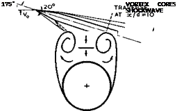 |
Fig. 5.37 Skeleton of flow past an inclined cone-cylinder body of revolution at Mq = 2.5. After Plascott & Treadgold (1955)
ce up to 90° and then back again, a strong hysteresis in the forces was observed, depending on the frequency and on whether the angle of incidence was increased or decreased. While the angle is increasing, there is an excess normal force over that in the static case but, for decreasing angle, the normal force is appreciably less than in the static case.


