THEORY – DYNAMIC LATERAL STABILITY
The theory for determining the dynamic stability characteristics of airplanes is relatively complex and lengthy, especially with all six equations of motion. The complete development of these equations and their analysis has been done by several authors (13,a, c,d) specializing on the subject of stability and control, and will not be repeated here. We will provide sufficient information for developing a basic understanding of the problem and show the important relationship of some of the stability derivatives. In the following section variations of the forces and moments leading to the stability dynamic derivatives will then be covered.
Basic Equations. In developing the equations of motion for an airplane certain simplifying assumptions are usually made. These are:
a) Second order terms are neglected — the disturbances are small.
b) The motion is steady about the symmetrical plane. The six equations of motion can be broken up into the longitudinal and lateral modes.
c) The changes in lift and moments due to changes in motion are instantaneous.
d) The controls are fixed.
|
(*Cnp>, |
|
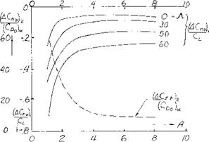
(ACnp)2 (^CDo)(* D°*(30) |
![]()
![]()
 |
 |
Roll
2ді (Кх2 Db20 + Kxz D2yO =
d d (271
+ 1/2 Cf p Db/ef+l/2(y D/
Yaw
2pb(K2 +KxZDb 0) =
Cn^’+1/2CnpD/+l/2CnrDb^ (28)
Sideslip
2^b(Db^+Db^) = Cyfi/9+ l/2CypDb/af+CL. Jzf+ l/2CyrDbi/’ + (CLtany)/’
|
Where /кб-= |
airplane relative density factor = (m/PSb) some authors use b’ for the wing semi span instead of b. |
|
к* = |
nondimensional radius of gyration in roll about longitudinal axis. |
|
nondimensional radius of gyration in yaw about the vertical stability axis. |
|
|
Db = |
differential operator (d/dsb) |
On the right hand side of the above equation the aerodynamic characteristics of the airplane are given while the moment of inertia, prodiict of inertia and acceleration are given on the left side.
Rolling Derivatives. In equations 27, 28 and 29 CW/c), Cj£p and Cyyo the derivatives due to the rolling velocity are encountered. These rolling derivatives are taken with respect to the effective helix angle of the wing and thus depend on both the forward and rolling velocity. The yawing moment due to roll is mainly determined by [128]
The vertical tail configuration to Cnpis found from the equation
C77(Bi=-(2i/bXz/b)Cy^ (31)
where Cygj – is determined considering the sidewash and effective tail length data of Chapter XIII.
|
Figure 20. Variation with aspect ratio and sweep angle of components required to find CL^with equation 30, from (13,d). |
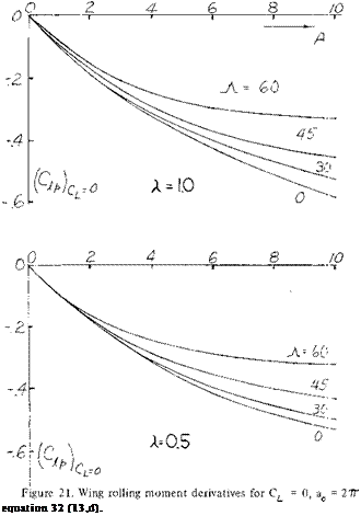
Damping in Roll The rolling moment due to rolling, C is mainly a function of the wing, sweep angle, taper ratio, and operating CL . Based on the method and data given in (13,d) which appears to be accurate and well accepted the Cjip can be calculated from equation 32 using the data of figure 21 to find Cat = 0. Equation 32 is then used to find the value of at the operating lift coefficient
C,
(CLaf)c L CL
(9?p)c|=o (C ) 8 Acos^t
^1 + 2 sin9
(32)
The slope of the lift curve for the wing CLa^ at CL =0 and the operating CL is found using the data given in Chapters II and III. The effect of high lift flaps on the damping in roll of the wing are accounted for by using the proper slope of the lift curve corresponding for these devices as determined from the data of Chapters V and VI. If the wing has tip tanks, corrections as presented in (13,d) must be applied to the calculated value of
 Yawing Derivatives. The derivatives of the yaw and rolling moments and the side force with the yawing motion, Cnr С*, and Cyr also appear in the equations of motion (27, 28 and 29). The damping in yaw derivative, Cnr is not greatly affected by the fuselage and wing as the velocity change due to yaw is relatively low. The vertical tail has a larger effect as it presents its flat surface to the motion. At moderate angles of attack the value of Cnr due to the vertical tail may be found from the equation
С-ЯТtai|_2(-£/b) Cy^ toil (35)
The side force derivative Cy^ is obtained from the data of Chapter XIII.
The rolling moment due to yaw, C^, is mainly effected by the wing and vertical tail. This occurs due to the angular velocity of the wings which cause an increase in lift on the advancing wing and a corresponding lift decrease on the retreating wing. These changes in lift result in a rolling moment which can be estimated for straight wings from equation (36) developed from the data of (13,d).
CL (.04A + .24) (36)
The effect of the vertical tail is estimated from the equation
C^ = -2(-*/b)C^to|1 (37)

The contribution of the horizontal and vertical tail to C^, can be estimated in a similar manner to the wing, however, the value is usually small and is neglected.
Lateral Force Due to Rolling. For a wing operating at conditions where the drag due to separation is low the derivative Cy/?, lateral force due to rolling, can be determined from equation 33.
Cy/> = Q_ [(A + cosA)/(A + 4 cosjY)] tanA+l/A (33)
The value of Cy/o at high lift coefficients from test data is lower than would be calculated from equation (33). At these conditions test data should be used if possible to find the lateral force derivative due to rolling. The lateral force derivative due to the vertical tail can also be estimated using equation (34). The side force derivative for the tail used in equation 34 is obtained from the data of Chapter XIII.
C yp tail =2(Z/b)Cyrai, (34)
The procedures for estimating the rolling derivatives given above apply only in the subsonic speed range.
In the case of the side force derivative due to yaw the theory appears to be inadequate so that experimental data should be used. The effect of the vertical tail however can be found from equation
Cy^ =-2i/b Cy/Itaii (38)
Dynamic Stability. The linear differential equations (27, 28 and 29) with constant coefficients are solved in the usual manner for these types, assuming that the following substitutions can be made:
j0o ew = jar, ^елт = , a =£
With these substitutions a characteristic equation for is obtained.
AA?+B A3+CXa + DX+E = 0 (39)
Where А, В, C, D and E are functions of the aerodynamic and mass properties of the airplane which in turn depend on the steady state flight conditions. It is shown in (13,a) there are four different types of motion depending on the roots of the characteristic equation (39).
1) When X is real and positive the motion increases steadily with time and the aircraft is unstable.
2) If X is real and negative the airplane is dynamically stable.
3) With complex root containing a negative real part, the motion is a damped oscillation tending toward zero.
4) When X is complex with a real part positive an increasing oscillation motion is obtained tending toward infinity, unstable.
Also when X is zero the motion persists undamped and if is complex with a zero real part, simple harmonic motion is obtained.

 |
 |
 |
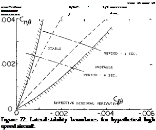
Based on the analysis of equation (39) to determine the characteristics of its roots presented in (13,b, d) stability boundary conditions can be set up for any airplane and operating conditions.
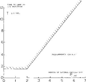
Some of the earlier specifications (14,b, c) relating to the desired flying qualities of an airplane used a criteria for time to damp to half amplitude as a function of the period of oscillation. This criteria, illustrated on figure 24, has been found to be unsuitable for elevating high performance aircraft as it does not adequately consider the pilots requirements. It has been found necessary to rely on pilots opinion to establish the proper damping ratio because of the complex inter-relationship between the airplane dynamics and the control function. Also, when operating with positive damping the lateral oscillation couples with a yaw oscillation and a sideslip, which gives a motion after a disturbance known as “Dutch” roll.
|
|
• і
Figure 24. Desired damping characteristics as a function of period of lateral oscillation (14,b, c).
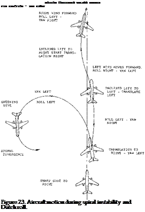
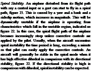
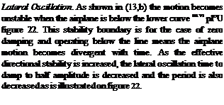
“Dutch” Roll. The “Dutch” roll characteristic of an airplane has become an important design consideration, especially with high performance and STOL aircraft. The “Dutch” roll is characterized by a rolling, sideslipping and yawing motion where the frequency about both axis is of the same order of magnitude but they are slightly out of phase. Thus, if we have a rolling motion as in figure 23, say to the right, with a corresponding sideslipping right yaw followed with a left roll and yaw where the yaw motion follows the roll, the airplane is in the “Dutch” roll mode. The frequency of the motion is much higher than for the spiral stability case. When the effective dihedral is very high in comparison to the directional stability the lateral-directional oscillation may actually become dynamically unstable and increase in amplitude.
Thus, in comparing the requirement for good “Dutch” roll characteristics with spiral stability a variance is noted between the need for high effective dihedral and directional stability.
Lateral Directional Stability – High Angles. Due to the stalling characteristics of swept wings, fuselage flow interaction on the tail, there have been many problems with lateral-directional stability when operating at high angles of attack. An example of the unfavorable characteristics of a jet fighter type airplane at high angles is given in (15,a). This airplane, figure 25, encountered directional divergence brought about by a simultaneous loss of directional stability and effective dihedral when operating at high angles of attack. This loss of directional and lateral stability is a part of one cycle of a highly unstable “Dutch” roll oscillation. The loss of the stability is caused by stalling of the leading wing panel at high angles and the adverse sidewash as illustrated in figure 25.
The “Dutch” roll instability time to damp to half amplitude, t1/2, and the period of oscillation, P, can be predicted based on theoretical methods (15,a) from the equations
P = 2 /d (b/v) (40)
T = -.693/c (b/v) (41)
Where c and d are the real and the imaginary parts of the root of the characteristic equation. When the quantity 1 /ti/2 becomes negative the airplane becomes dynamically unstable as illustrated in figure 24. To accurately find the roots of the characteristic equation and thus find the resultant instability it is necessary to find the many derivatives of the airplane as a function of angle of attack. At high angles of attack where separation of the flow is encountered it is necessary to use wind tunnel test data to find the derivatives and thus evaluate the stability. And here Re and M and roughness are subject to scale effects.
(15) Complete Airplanes:
(a) Chambers and Anglin, Lateral-Directional Stability of a Fighter Airplane, NASA TN D-5361.
(b) Heinle, Lateral Oscillation Several Aircraft, NACA RM A52J06.
(c) Campbell & McKinney, Aircraft with Satisfactory Dutch Roll Oscillation, NACA TR 1199.
(d) Ray, Large Sideslip Angles – T-Tail Transport, NASA TM X-1665.
(16) Lateral-Directional Handling Qualities:
(a) Ashkenas & McRuer, Handling Qualities from Pilot – Vehicle Considerations, Aerospace Engineering, Feb. 1962.
(b) Ashkenas, Lateral-Directional Handling Qualities, US AFFDL-TR-65-138, Part II, Nov. 1965.
(c) Miller & Franklin, Lateral-Directional Flying Qualities for Power Approach, J. Aircraft Vol 5. No. 2 1968.
(d) Vomaske, Sadoff and Drinkwater, Lateral-Directional Couplings — Fixed-Base Simulator, NASA TN D-1141.
(e) Teper, Lateral-Directional Handling Qualities, J. Aircraft May, June 1966.
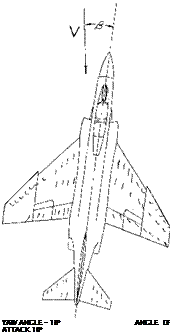 STALL TAKES PLACE ON LEADING WING PANEL AND CAUSES A LOSS OF EFFECTIVE DIHEDRAL.
BEHIND STALL, FLOW IS REVERSED CAUSING A LOSS OF TAIL EFFECTIVENESS AT HIGH ANGLES OF ATTACK.
Figure 25. High performance fighter aircraft at a high angle of attack and yaw angle.
4. LATERAL DIRECTIONAL FLYING QUALITIES
The basic flying qualities of an airplane must be satisfactory throughout the operating range especially with high performance STOL and fighter type airplanes. Operating problems at the low speed landing condition and at high altitudes are caused by low damping conditions when operating at high lift coefficients. In cruising flight problems are encountered due to low damping which are a direct function of the geometric characteristics of the airplane. These problems have often led to the use of artificial mechanical stability augmentation systems (SAS). Although it is desirable to design the airplane to have the desired basic stability this is not always possible, so that SAS systems become a requirement. In fact, most modern high performance swept wing aircraft use SAS systems to obtain the desired level of stability and so reduce the work load of the pilot.
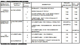
Pilot Ratings. Because of the opposite requirements of the levels required of effective dihedral, C^ , and directional stability, СП£ , it is necessary to use pilot ratings to establish the best configuration and the gains needed in the SAS system. Pilot ratings based on the Cooper ten point rating system (17,a) are very effective and consistent for evaluating a configuration. As noted on table 1, the Cooper rating system judges a configuration in terms of the ease of flying the airplane. A rating of 1 is the best and 10 the worst. Cooper ratings are obtained by the operation of flight simulators, variable stability test airplanes or the actual airplane being evaluated (17). The degree of correlation of the ratings between the various methods depends on the level of simulation used and are usually quite consistent in trend. To provide the data for evaluating new designs the pilot ratings must be related to the aerodynamic characteristics of the airplane as discussed in (16,b).
 Aircraft Handling Qualities. Investigations have been made to determine the characteristics of the control system and the inherent stability to obtain high pilot ratings. These investigations (16) have been made to determine the specific parameters best suited, such as roll damping and roll acceleration for correlation with pilot ratings. Such correlations are incorporated into aircraft design specifications that the designer must meet. If the constraints of the configuration or its operation are limiting in achieving the desired stability it may be necessary to obtain the needed characteristics with a SAS system. SAS systems have been used on many high performance aircraft, including most STOL and VTOL types. Any information available which relates Cooper rating to period, tor stability derivative combination would be very useful.
![]()


