Three-Dimensional Effects on Dynamic Stall
As discussed earlier in this chapter, in the rotor environment the problem of dynamic stall must be considered as fully three dimensional. Stall will occur over different parts of the blade and at different blade azimuth angles, and needless to say, the resulting flow can be very complicated. Apart from the 3-D effects associated with swept flows, the
problem of 3-D unsteady separating flows are still poorly understood. As mentioned earlier, the various mathematical models used for dynamic stall prediction are still heavily empirical, with reliance being placed almost exclusively on oscillating 2-D airfoils for formulation and validation purposes. It is only recently that attempts to validate these models has been made for 3-D dynamic stall problems, albeit these are still very much idealized problems compared to those found in the helicopter rotor environment.

The problem of 3-D dynamic stall has been studied experimentally by Lorber et al. (1991), Lorber (1992), Pizialli (1994), and Berton et al. (2003a, b) and computationally by Spentzos et al. (2Q04). Lorber and Pizialli have used a cantilevered semi-span wing that was oscillated in AoA through stall and like the 2-D tests, was designed to simulate the variations in AoA encountered by a helicopter rotor blade. Miniature pressure transducers
 (3) 2
(3) 2
1.5 O*
1
0.5
0
 |
 |
were distributed at various stations along the wing, and the measured pressures have been integrated to determine sectional lift, drag, and pitching moment. While Pizialli’s results are limited to a Mach number of 0.3, Lorber’s results cover a wider range of Mach number from 0.2 to 0.6 and also for wing sweep angles of 0, 15, and 30°. Berton et al. (2003a, b) and Spentzos et al. (2004) have also examined the dynamic stall of wings with finite span.
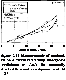
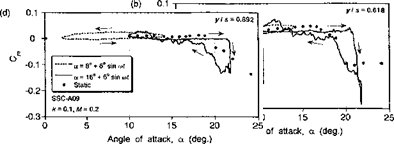
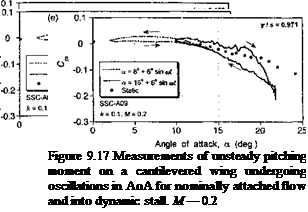
Representative results from the 3-D dynamic stall experiments of Lorber et al. (1991) are shown in Figs. 9.16 and 9.17. These results document the unsteady lift and pitching moment coefficients at five spanwise stations from near the mid-span out toward the tip of the wing. Results are shown for an oscillation below stall and for a typical case of dynamic stall at the same reduced frequency. The static measurements at each station of the wing are also shown for reference. For oscillations below stall, characteristic elliptical hysteresis loops are formed with no particularly unusual behavior compared to that expected from 2-D considerations. Notice, however, the gradual reduction in the average lift-curve – slope when moving outboard toward the tip, although this is a quasi-steady effect and would be predicted by any finite-wing model. The only exception is at the outermost wing station, where both the steady and unsteady lift and pitching moment hysteresis loops show a different characteristic, with a more nonlinear quasi-steady behavior. This is the influence of the tip vortex, which lies over the tip region and provides an element of
steady vortex induced lift. Other than for this one section of the wing, unsteady thin-airfoil theory, with the quasi-steady induced effects accounted for by a lifting-line or other finite – wing method, will provide a good approximation to the unsteady airloads – see Tan & Carr (1996).
The dynamic stall characteristics on 3-D finite wings are noted to be qualitatively similar to those found on oscillating 2-D airfoils. Figures 9.16 and 9.17 show that at the four inner stations, the airloads exhibit the lift overshoots, large nose-down pitching moments, and hysteresis effects that are characteristic of 2-D dynamic stall. Notice that when moving outboard from the innermost station the degree of dynamic stall penetration is reduced. Again, this is mainly a steady effect associated with the reduction in the effective quasisteady AoA because of the induced effects from the tip vortex. In fact, the results appear qualitatively similar to those obtained with a reduction in the mean AoA in the 2-D case. While lift and pitching moment overshoots are also obtained at the outermost station, the results are less transient suggesting that leading edge vortex shedding does not occur. In fact, it would appear that the tip vortex alone dominates the flow field here and the AoA never becomes large enough to permit stall to occur in the normal sense.
Overall, the results in Figs. 9.16 and 9.17 indicate that if the wing aspect ratio is relatively high then the oscillating finite wing problem can still be considered nominally 2-D as far as dynamic stall is concerned, and 2-D models with appropriate allowance for the induced distribution of AoA associated with finite span should give at least engineering levels of predictive capability. This has been confirmed by results shown by Tan & Carr
(1996) , who compare results of the Pizialli experiments with a number of the better known semi-empirical dynamic stall models, some of which have been described previously. However, this conclusion is based only on a limited validation study, and much further work still needs to be done to analyze the problem of 3-D dynamic stall if credible predictions of helicopter airloads are to be improved. The problems are further compounded by the centrifugal and Corriolis effects that are produced on the 3-D boundary layer developments on rotating blades. The issues seem particularly acute on wind turbines, which often operate with substantial amounts of dynamic stall compared to a helicopter rotor – see Section 13.12.2.


