Two Dimensional Transonic Flow, Local Linearization
The linearized potential Eq. 2.24b was obtained under the assumption that the difference between the free stream speed of sound and the local speed of sound a’ was negligible. When the free stream Mach number M? approaches unity this difference becomes important, therefore, it has to be taken into consideration for transonic flows. Integrating the linearized form of the energy equation, Eq. 2.24b along a streamline from the free stream to the point under consideration, gives the relation between the local speed of sound and the perturbation potential as follows
 (6.1)
(6.1)
Substituting Eq. 6.1 for the local speed of sound in Eq. 2.24a provides us the perturbation potential for the transonic flow in terms of free stream speed of sound in open form in following manner
Here, the second derivatives are given in indicial notation. The first term of Eq. 6.2 makes the equation nonlinear. In addition, the difference expression а2ж — U2 under the bracket of the first term becomes very small as Mach number goes to zero. This makes the first derivative terms to remain in the bracket. After this simplification of Eq. 6.2, we can divide it by а2 to obtain
MN in Eq. 6.3 is given as
m2 = mIA1 + "A^uA/x
Here, the time derivative in the first term is neglected; however, the equation is still nonlinear. Equation 6.3 still contains time dependent terms at its right hand side and it can be used in studying unsteady transonic flows.
Now, we are going to introduce the local linearization concept for the solution of Eq. 6.3. For this purpose let us separate the perturbation potential into its steady and unsteady components in following manner: /’ = /S + /d, where subscript s denotes steady and d denotes the unsteady components. The steady component of the perturbation potential from the left hand side of Eq. 6.3 satisfies the following homogeneous equation.
(1 — M2 )/Sxx + /Syy + /Szz = 0 (6.4)
The unsteady component, on the other hand, reads as
/dyy + /dzz — OrAitt — £^ — e/dxx — f /dx = 0 (6.5)
denotes partial differentiation, whereas subscripts s and d stand for steady and unsteady components as before.
In Eq. 6.5, coefficients e and f contain the partial derivatives with respect to x only; therefore, they can be expressed in terms of the pressure coefficient for the steady part using Eq. 2.21 as Cp = —2/X/U. Let us remember once more that
Eq. 6.5 is non linear because of e and f, Therefore, Eq. 6.5 can be solved either numerically or by means of local linearization (Dowell 1995). For two dimensional studies in x—z coordinates, the local linearization is made as follows. We first decompose the steady perturbation potential into its two different components as follows: ф’ = ф° + ф. In addition, let us expand coefficients e and f into (x — x0) power series as follows
e = em(x – x0)m vs. f = fm(x – x0)m
m=0 m=0
Now, for obvious reasons, the homogeneous equation is used with the non homogeneous boundary conditions, i. e.,
ф0 – е0ф°ж – f0/0 = °. (6.6)
The non homogeneous equation to satisfy the homogeneous boundary conditions, i. e.,
11
^zz – e0 Фxx – f0 h = ф0ж +^xx em (x – x0)m + ( ф0 + ^x) fm(x – x0)m
m=1 m=1
(6.7)
For a good approximation, we expect: ф0 ^ ф. In order to satisfy this condition the choice of x0 plays an important role in determining coefficients e and f. Another important fact here is that the first terms of e and f are independent of x, which means the value of e0 is a constant. Approaching from supersonic side will make the sign of e0 positive, and subsonic side will make it negative. Now we know that free stream conditions being slightly supersonic causes the perturbations from a point to be felt only in downstream Mach cone of that point. Utilizing this fact enables us to use unilateral Laplace transform in x direction for Eq. 6.6 with prescribed non homogeneous boundary conditions. The definition of Laplace transform of 0 in x is given as
1
ф0 = J Z°(x, z)e-sxdx 0
As is known the Laplace transform of a derivative of a function is given by initial conditions times the powers of s, powers being proportional with the order of the derivative. Applying this property for Eq. 6.6 gives us the following second order ordinary differential equation
ф° -(e0s2 + f0s)ф0 = 0 (6.8)
Taking i2 = (e0s2 + f0s) gives the solution of Eq. 6.8 as follows
ф 0(z)=Ae-1z + Be1z (6.9)
In order to satisfy the diminishing radiation condition at infinity in Eq. 6.9 taking B = 0, for upper surface will be consistent with the physics of the problem. On the other hand, the coefficient A can be obtained from the transformed surface boundary condition. For this purpose we match the downwash, w, with the z derivative of the perturbation potential, expression 6.9, at z = 0+ as follows
^(z = 0+) = W and ф0(z = 0+)= — (6.10a, b)
oz l
Here, inverse Laplace transform of Eq. 6.10a, b is performed to express the perturbation potential since the downwash and i are expressed in s. Here, we have to note that i2 is always positive. The variable s is also by definition greater than zero. Hence, the convolution integral (Hildebrand) gives the inverse of Eq. 6.10a, b as follows
X
/0(z=0+)=- у e01/2exp(-2“)/o (2£)w(x – n)dn (6Л1)
0
Here, Z0, is the 0th order first kind modified Bessel function (Appendix 5). As the surface boundary condition, the downwash w is prescribed; therefore, the pressure coefficient along the chord can be found by integral 6.11. As Mach number goes to 1, the value of e0 approaches infinity; however, the exponential function of the integrand and the Bessel function simplify the integral 6.11 as follows
X
/0(z = 0+) = — f-1/2(nn)-1/2w(x – “)d“ (6.12)
0
Let us determine the perturbation potential for a thin airfoil at a = constant angle of attack for the upper surface, z = 0+, using 6.11. The downwash, w = — Ua, gives the integral 6.11
1 2e1/2 f
/0(z = 0+)— = ехр(-П)[Ш + Ш], n = 2f-x (6.13)
The upper surface pressure coefficient reads as
q0
~ap =-2Є-1/2exp(-“)/0(“) (6.14)
The lower surface, on the other hand, has negative z value; therefore, in Eq. 6.9 the radiation condition is applied accordingly to obtain the following lower surface pressure value
Equations 6.14-6.15 give the lifting pressure expression as follows
Ac0 _,/2
– = 4e°1/2 exp (-П)Іо (П) (6.16)
a
Integrating 6.16 along the chord provides us the sectional lift coefficient as
C° = 4a(f0 b)-1/2 b1/2 exp (-b)[Io (b)+h (b)], b = —. (6.17)
e0
Here, b represents the half chord.
Since we know the perturbation potential component, /0 related to the non homogeneous boundary conditions, we can now write the following equation for ф using Eq. 6.5
-f0- e0Фxx = e1 (x – Xo)/0°x (6>.Щ
In order to solve Eq. 6.18, we again take the Laplace transform of it with respect to x coordinate to obtain a non homogeneous second order ordinary differential equation
ф – l2Ф = -e^2s/0 + + xos2ф^ (6.19)
As a technique, first we solve the homogeneous part of Eq. 6.19, and then obtain the non homogeneous solution. The homogeneous part is solved exactly like Eq. 6.9. After finding the general solution of Eq. 6.19 under homogeneous boundary conditions we can take the inverse Laplace transform of the result to obtain the solution in x coordinates. The downwash expression, w = -Ua, from the surface boundary condition gives us the perturbation potential and that in turn provides us the surface pressure coefficient as follows:
C- ffi ae-3/2exp(-n) [2П(І1 – І0)+10] (6.20)
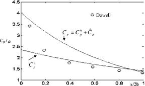
In Fig. 6.1, plots of C0 given by 6.15, Cp given by 6.20, and their summation as the total surface pressure distribution for Cp is shown for Mach number 1. On the
 Fig. 6.1 The surface pressure coefficient obtained with local linearization at M? = 1 (with x0 = 2b, f0 = 2.4/b,
Є0 = 0.72)
same figure also shown is the surface pressure obtained by Dowell using Stahara – Spriter’s calculations for 6% thick Guderly airfoil (Appendix 6). In this comparison, coefficients e and f are expanded into the series about x0 = 2b. Here, value of x0 is chosen arbitrarily; therefore, to calculate the pressure coefficient properly calibration with other methods is necessary (see Problem 6.9).


