Wing-fuselage interference
5.6 There is an extensive literature on the aerodynamic interference between wings and fuselages, and much material has been collected together in outstanding summary reports and surveys by HR Lawrence & A H Flax (1954), H Ashley & M T Landahl (1965), T E Labrujere &
H A Sytsma (1972), H Ashley & W P Rodden (1972), and R C Lock (1973). See also the papers published in AGARD CP-71 (1970) and the bibliography by P A Newman & D 0 Allison (1971), Recent years have seen the development of numerical methods which can deal with inviscid incompressible flows past wing-fuselage combinations. In general, these use in various ways distributions of singularities on discrete panels, replacing the continuous surface of the combination, and we refer to the methods by J L Hess & A M 0 Smith (1967), F A Woodward (1968), W Kraus & P Sacher (1970), T E Labrujere, W Loeve & J W Sloof
(1970) , В Maskew (1970), H Komer (1969), (1972), and (1975), and A Roberts &
К Rundle (1972) and (1973). Here, we want to concentrate our attention on those flow phenomena which must be known and understood when it comes to the design of an aerodynamically well-behaved wing-fuselage combination. The approximate theories discussed below, which allow some physical interpretation, serve this purpose best.
Interference effects are always largest in the function between intersecting bodies, and any worthwhile theory must get the behaviour in the junction right and properly represented. Therefore, we discuss first the flow along the junction between a wing and a fuselage which is assumed to be cylindrical and infinitely long. There are four main effects, all equally important in practice:
1 Displacement effects, arising from the thickness of the wing and the curved intersection lines.
2 Lift effects^ arising from the circulatory flows around wing and fuselage.
3 Effects of asyrrmetry3 associated with the shape of the cross-section of the fuselage or with the position of the wing on the fuselage (mid, high, or low position).
4 Effects of viscosity over and above those present on the bodies in isolation, arising from the viscous flows along the corner formed by two walls.
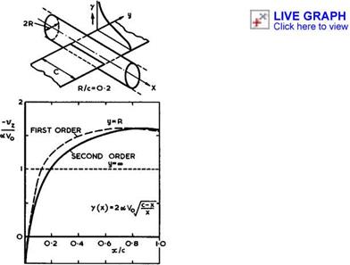
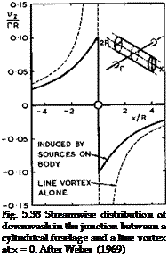
We consider first the lift effects so as to dispose of the far-too-simple notion of aerodynamic interference described at the beginning of Section 5.5, based on exact solutions obtained by J Lennertz (1927) and F Vandrey (1937). Consider again the flow past an infinite circular cylinder whose axis is parallel to the mainstream, with an infinite line vortex normal to the mainstream, which passes through the axis of the cylinder and induces velocity components normal to the surface of the cylinder. This configuration is sketched in Fig. 5.38. One method to compensate for these interference velocities and to make
 LIVE GRAPH
Click here to view
the cylinder into a streamsurface again is to place a suitable continuous distribution of sources on the surface of the fuselage. This method has been developed in detail and made into a practical routine procedure to deal with the general interference problem, which can readily be incorporated into the RAE Standard Method, by J Weber (1969), and J Weber & M G Joyce (1971), and (1974). The wing is then subjected to the velocity field of the source distribution on the fuselage. No downwash is induced at the line vortex, which is the basis of the mistaken "no-overall-interference" statement made above. The mistake can readily be discovered by calculating the complete downwash distribution along the junction with a wing of non-zero chord. As can be seen from the results in Fig. 5.38, the downwash is not zero as the line vortex is approached from either side, even though it is zero at the line itself. As a consequence, a complete theory, where the wing is represented by a chordwise distribution of bound vortices, leads to a continuous non-zero downwash distribution in the junction. This means, in turn, that either the chordwise and spanwise load distribution on a given wing are changed by the fuselage interference, or that the wing must be cambered and twisted if the initial loading
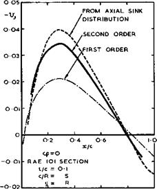
on the isolated wing is to be maintained everywhere (see D KUchemann (1967)). This interference effect is large, as can be seen from the example in Fig. 5.39, where the wing is assumed to be a thin flat plate far away from the
|
Fig. 5.39 Streamwise distribution of the downwash in the junction between a cylindrical fuselage and a (flat-plate) vortex distribution. After Weber (1969) |
junction. The downwash induced in the junction is then far from constant. If the wing is to remain a flat plate right into the junction, the chordwise and spanwise loading will have to be calculated in this downwash field. These will differ significantly from the twodimensional flat-plate loading. An iterative procedure will have to be carried out because the source distribution over the fuselage, to cancel the normal velocity component there, will have to be adjusted to the velocity field of the changed loading over the wing. Alternatively, if the wing is to retain its twodimensional flat-plate loading all along the span, it will have to be cambered and twisted according to the variation of the downwash along the chord. Note that these effects already arise when the fuselage shape itself is so simple that it does not disturb the mainstream. Much more complex interference effects must be expected to occur on real fuselages. We note also that, once again, the concept of a "lifting line" is not only insufficient and unnecessary but also misleading and that it can cause serious errors when applied to the nearfieId.
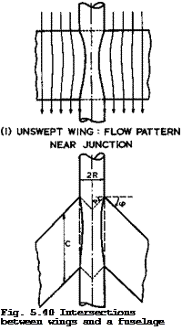
Consider now displacement effects, again first for an infinitely-long cylindrical fuselage which, by itself, does not disturb the flow. In the general case, where the wing thickness t in the junction is not small as compared with the diameter 2R = d of the fuselage, the intersection lines will be curved significantly, as sketched in Fig. 5.40 (1). This will be associated with an interference velocity increment Vj in the junction, provided the flow follows the curved intersection lines, which usually applies if the intersections are not too shallow, that is, if the body diameter is more than, say,
twice the wing thickness.
 |
(2) SWEPT WING : CONTINUATION
OF WING INSIDE FUSELAGE
This displacement effect manifested itself in a different form in calculations where a source distribution, representing a fuselage, was superimposed on a source distribution, representing an unswept wing. The resulting shape of the combination was determined by exact streamline tracing, by J Liese & F Vandrey (1942). This shape exhibited a pronounced bulge outside the original fuselage in the region of the junction where the fuselage now merged into the wing.
In the absence of fuselage sources, the fuselage itself would be formed of streamlines of the wing flow. This kind of fuselage shaping has been advocated as a general design principle for unswept wings by H Muttray (1934) and also for swept subcritical wings by D Kuchemann (1947), W F Hilton (1955), and again by C L Bore (1971), on the grounds that this would produce a clean flow in the junction without adverse interference effects. Such streamline shaping can readily be applied when d » t, and has been found effective. The method is not unique in the general case because a particular bunch of initial streamlines far upstream of the wing may be chosen arbitrarily, representing different cross sections (and nose shapes). This freedom of choice may be an advantage in practical cases. Like other design methods, this one applies only at one particular design condition.
The bulge referred to above is obviously caused by a local "surplus of sources" within the body in sections x = constant. If the original fuselage shape is to be maintained, e. g. if it is to remain a cylinder, then the wing sources
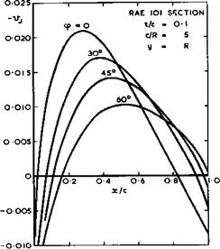
inside the fuselage should be taken out. The simplest way of doing this is to put a sink distribution along the axis of the fuselage, the strength of which is equal and opposite to the total of the wing sources inside the fuselage in section x – constant. This very crude kind of area treatment is surprisingly accurate (see D KUchemann (1947), D KUchemann & J Weber (1953)). This can be seen from the example in Fig. 5.41 of an unswept wing on a cylindrical fuselage with d/t = 4. The streamwise velocity increment Vj is shown, as calculated by the area method and also by Weber’s theory referred to above.
For the latter, both first-order and second-order approximations are given. In the first-order approximation, the velocity field is computed, and the boundary conditions are fulfilled, on the chordal plane of the wing, as in linearised wing theory; in the second-order approximation, this is done on the surface of the wing. It is evidently important to include second-order terms in
|
Fig. 5.41 Interference velocity in a wing-fuselage junction at zero lift |
Consider now the junction effects when the wing is swept. A new feature is then that the wing section at the intersection tends to behave like the centre section of a swept wing (see D KUchemann (1947), D KUchemann & J Weber (1953)). This arises from the reflection of the wing in the surface of the fuselage, as can readily be seen in the limiting case d/t •+ « , i. e. when the wing is reflected in a plane wall (see also J W Craggs & К W Mangier (1971)). Such a reflection effect remains also in the case of a curved wall and it is, therefore, important to represent this local behaviour correctly in any theory.
This can readily be done in Weber’s theory by considering a kinked wing plan – form, as sketched in Fig. 5.40 (2). Note that the wing inside the fuselage is not the true reflection of the complete wing in the wall of the fuselage – this would be a much more complex curved shape. The aim in Weber’s method is to represent only the local reflection effect in the junction itself; for this, the shape considered is sufficient.
The velocity increments in the junction then consist not only of the term Vj, arising from the source distribution over the fuselage needed to make this into a streamsurface, but include two further terms arising from the wing flow:
Vg, the velocity increment over the corresponding sheared wing of infinite span; and v^ , the velocity increment due to the centre effect caused by the reflection. For the displacement flow considered here, vs and v^ are the two terms in (4.86), to a first order, or in (4.88). It is easy to see how the interference terms may be generalised and incorporated into a general relation.
![]() Sweep does not only introduce the centre effect in the junction but also affects the value of vj(x). The changes in Vj due to sweep may be quite large, as can be seen from the example in Fig. 5.42. These curves have been calculated by Weber’s first-order theory, the curve for zero sweep being the same as that in Fig. 5.41. If Vj is calculated by the approximate area method of putting compensating sinks along the axis of the fuselage, the strength of the sink distribution should have an overall factor cos <p, as proposed by D A Treadgold (1970, unpublished).
Sweep does not only introduce the centre effect in the junction but also affects the value of vj(x). The changes in Vj due to sweep may be quite large, as can be seen from the example in Fig. 5.42. These curves have been calculated by Weber’s first-order theory, the curve for zero sweep being the same as that in Fig. 5.41. If Vj is calculated by the approximate area method of putting compensating sinks along the axis of the fuselage, the strength of the sink distribution should have an overall factor cos <p, as proposed by D A Treadgold (1970, unpublished).
|
Fig. 5.42 Interference velocity in wing-fuselage junctions according to first-order theory at zero lift |
For fuselages of finite length, the source distribution along the axis or the surface distribution of sources may be continued to represent the front part as well as the rear part. When the fuselage shape has a cylindrical middle part and a distinct forebody and a distinct afterbody, as in many practical cases, it is convenient to think of the velocity along the junction as being composed of the following elements:
Vx> “ v0 + vx = V0 + VB + VJ + VS + Vc ’ (5-26)
where Vj is then restricted to the velocity increment due to interference with a cylindrical fuselage, and where Vg represents the contributions from the forebody and the afterbody. Every one of these terms has its own physical interpretation and meaning and, as will be seen below, one may be played against another to achieve certain design aims. For instance, junctions may be shaped so that Vj cancels v^ . One does not learn much if the four different terms are all lumped together in one numerical answer.
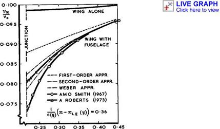
Using any of these methods of representing wing and fuselage by singularities, we may calculate the complete inviscid, incompressible velocity field, in principle to any desired accuracy. In practice, the computational effort needed sets some limits. Weber’s method has been developed to a first-order and to a second-order accuracy and also to some alternative approximation which is especially convenient for practical purposes. These three approximations are shown in Fig. 5.43 for the variation of vx along a spanwise line on a particular sweptback wing. Also shown are results from two panel methods, by
|
У/Сс Fig. 5.43 Calculated velocity increments on the wing-fuselage combination of Fig. 5.46 |
J L Hess & AH 0 Smith (1967) and by A Roberts & К Rundle (1972), which require considerably longer computing times. The latter method should be inherently more accurate than the former, especially since the correct analytical reflection behaviour near the junction has been incorporated into the program, as in Weber’s method. It appears that an ordinary method with planar panels of constant strength may lead to significant errors, and it is doubtful whether these can be reduced simply by increasing the number of panels. It is obviously preferable to determine analytically the behaviour in critical regions, such as junctions, and to build this into a computer program, for the sake of accuracy and of saving time. On present evidence, the method of Weber & Joyce is demonstrably the most powerful, combining physical realism for design purposes with high accuracy and computing economy. It is not quite complete, however, and extensions are desirable to include fuselages of finite length and non-circular cross-sections and to combine it with Sells’s iterative procedure.
Considerable simplifications could be made if the configuration could be regarded as slender, i. e. if the perturbations are small and if, in addition, the gradient with respect to x of the streamwise perturbation velocity component is small compared with the corresponding gradients of the lateral comr ponents with respect to the lateral ordinates. This is obviously not true, in general, for the combinations of bodies and swept wings considered here, except perhaps at transonic speeds where they may be regarded as aerodynami-
cally slender, within the assumptions of small-perturbation theory (see e. g.
J R Spreiter (1950), G N Ward (1955), R T Jones (1956), MacC Adams & W R Sears (1953), S S Stahara & J R Spreiter (1972)). As explained in Section 4.8, the equations of motion then reduce to (2.28) with 8=0 and only require the calculation of a twodimensional incompressible flow in planes across the configuration. But, as in the case of wings alone, the results may not be realistic.
The calculation of corrpressible siiberitical flows is, as usual, rather uncertain. The Prandtl-Glauert procedure may be applied and the flow past the analogous wing-fuselage combination calculated. When the various terms are split up and can be identified separately, as in (5.26), then improved compressibility factors may be applied to all the terms.
Another theory, which can also be applied for design purposes, has been developed for those configurations where the fuselage contribution to the flow along the junction may be regarded as being caused by a quasi-aylinder of infinite streamiise extent (see the summary papers by J A Bagley (1961) and by R C Lock & J Bridgewater (1967)). At siibsonie speeds, the velocity field of such a shape can conveniently be calculated by using a distribution of vortex rings over a cylindrical surface in the region of the junction. The velocity fields induced by distributions of vortex rings are well known (see D Kuche – mann & J Weber (1943), F Riegels (1952)). However, if this scheme is applied in such a way that the shape y(x) of the intersection line is taken to define the radius of a body of revolution and the whole body is presumed waisted in this manner (as in D Kuchemann & J Weber (1953)), then the junction effect may be overestimated, – the methods described above, such as Weber’s method, should be more reliable. On the other hand, quasi-cylinder theory appears to give better results at supersonic speeds. Here, a method for calculating the flow past bodies of revolution due to M J Lighthill (1945) may be used (see also CHE Warren & L E Fraenkel (1955)), and a complete theory has been developed by D E Hartley (see D Kuchemann & D E Hartley (1955)). D G Randall
(1955) and (1963) extended this work to deal with quasi-cylindrical bodies of arbitrary cross-sectional shapes. J N Nielsen (1952) developed a basically similar method and extended it so that the whole velocity field around a body may be calculated, not only the velocity on the surface. The availability of extensive tables of the required functions (J N Nielsen (1957) and W A Mersman
(1959) ) made it also possible to design a fuselage shape to produce specified velocities not only in the junction but also at points on the wing away from it, and J G Jones (1959) described a practical method of doing this. For wing – fuselage combinations of given shape, Nielsen’s method can be used in the same way for supersonic speeds as Weber’s method for subsonic speeds. The correct reflection behaviour at the junction can be ensured if the wing is continued inside the body in the manner shown in Fig. 5.40 (2). J A Bagley (1961) has shown what happens if only the reflection effect is taken into account, and D A Treadgold (1966) has demonstrated the effect of disturbances reaching a junction around the body from the halfwing on the other side of the fuselage.
On the whole, the various physical interference effects, described above for subsonic flow, are found again in attached supersonic flows, except that there is now no "sheared-wing" term as in (5.26), because only the Ackeret term proportional to the local slope remains at the centre section of a swept wing.
Mathematical problems associated with supersonic flow past wing-fuselage combinations have been treated by К Stewartson (1951, unpublished) (see R T Waech – ter (1969), R W Clark (1970) and references given there). The solution to the flow problem in the neighbourhood of the surface is related mathematically to
that of short-wave diffraction by a cylinder, but the application is to wings with supersonic leading edges, which are not considered here.
Various relaxation methods, based on the transonic small-perturbation equation (TSP), which have been described in Section 4.8, can also be applied to wing – fuselage combinations. E В Klunker & P A Newman (1974) and S Rohlfs & R Vani – no (1975) developed such methods to include supercritical wing flows, and A Gustavsson & R Vanino (1975) designed and tested a wing-fuselage combination with a supercritical aerofoil section.
Before we go on to look at some experimental evidence, we must be aware of the effects which viscosity may have, especially on the flow near the junction.
There are, in the first place, significant differences from flat-plate boundary layers because the viscous region now extends along a corner between two walls inclined to each other at some angle. Such flows have been investigated mainly for the special case where the static pressure is uniform throughout the field (see e. g. A D Young & M Zamir (1970), 0 0 Mojola & A D Young (1971)).
A secondary flow then develops in the viscous layer near the corner, with velocity components towards the corner close to the walls and outwards from the comer in the plane of symmetry, if the flow is laminar. The sign of the transverse flow is reversed after transition to turbulence. This secondary flow affects transition as well as separation, especially since the skin friction appears to drop to zero as the corner is approached. F В Gessner (1973) investigated the origin of the turbulent secondary flow in detail.
Even more complicated situations occur in wing-fuselage junctions, where the pressures tend to different values away from the junction. In addition, another important effect of viscosity must occur in any junction which, in inviscid flow, would contain a singular stagnation point. This applies in all the cases considered here, where wings with round-nosed subsonic leading edges intersect the wall of a fuselage. The approaching boundary layer along the fuselage will not be able to run up against the adverse pressure gradient to full stagnation pressure but will separate before it reaches the leading edge.
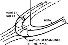
At high-enough Reynolds numbers, the resulting threedimensional separation surface may be a vortex sheet originating from a separation line on the fuselage, which contains a singular separation point upstream of the leading edge
|
Fig. 5.44 Flow near the intersection between a body and a wall |
and then continues as an ordinary separation line wrapped around the junction, as sketched in Fig. 5.44. The free edge of the vortex sheet will roll up into cores on either side of the wing. If the Reynolds number is relatively low,
a thin vortex sheet cannot be expected to be an adequate representation of the separation surface, but separation lines as in Fig. 5.44 are likely to persist and vorticity is likely to be concentrated and submerged within the viscous region. In any case, the viscous region near the junction then loses altogether the properties of a boundary layer; and it will change the pressure field throughout the region in a manner quite different from the usual displacement effect of ordinary boundary layers. There is no way as yet of calculating this important effect.
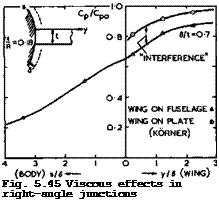
Some experimental evidence on how large this viscous junction effect can be is presented in Fig. 5.45, from tests by L F East И P Hoxey (1968) and H Kbrner
(1969) (see also D KUchemann (1970)). There are two cases and in both a nonlifting, wing-like, body of thickness t is joined either to a plane wall or
LIVE GRAPH
 |
Click here to view
to a flat thin plate at right angles to it or to a circular fuselage of radius R. The thickness of the approaching boundary layer is 6 . The pressure coefficient – Cp (in the region of the suction peak on the wing) is seen to fall below its value Cp0 on the wing far away from the junction as the junction is approached, even when the intersecting wall is flat and would not disturb an inviscid flow. In the junction itself, the pressure is only about 3/4 of the undisturbed value on the wing, in both cases with plane walls. The upper part of Fig. 5.45 shows how the pressure then approaches an inverse square law with distance from the wing. It also shows clearly two suction peaks which, we may infer, are induced by the vorticity concentrated along the separation surface, even though we do not know the structure of the separation surface in detail in this flow where it is likely to be submerged within the
viscous region. This feature is not normally picked up in model tests in wind – tunnels such as those in the lower part of Fig. 5.45, and it has been missed altogether in most tests. The magnitude of the viscous interference effect is much the same in both cases shown in Fig. 5.45, although the values of 5/t and of the Reynolds number differ widely.
When the wing joins the curved wall of a fuselage, along which the boundary layer is much the same as that along the plate of the same length ahead of the wing, the lower curve in the lower part of Fig. 5.45 is obtained. The difference between the two curves there may be interpreted as having been caused by the interference effects in inviscid flow discussed above. We find that this interference pressure is of the same order as the viscous interference in the junction. But the two effects are likely to fade out in different ways away from the junction: the distance from the junction should be measured in terms of the fuselage radius for the interference in inviscid flow, and in terms of the (much smaller) thickness of the approaching boundary layer in viscous flow. Nevertheless, the magnitude of the viscous interference effect is such that it cannot be ignored, and we should not be taken in by any claims to "good agreement" between measured results and any calculated for inviscid flow and come to false conclusions as to the accuracy of any such theory – these results should not agree. To throw more light on viscous interference effects, by experiment and by theory, is evidently an important task for future research.
The uncertainty about viscous interference should be borne in mind when we now look at some of the meagre available experimental evidence.
Experimental results, which are suitable for our purpose,, have been provided by, among others, D E Hartley (1952) and (1953), J E Rossiter (1959), A В Haines & J С M Jones (1960), T E В Bateman & D J Harper (1960), W R Buckingham (1961), G К Hunt (1963), H Kbmer (1969), J I Simper & P G Hutton (1970), W Schneider
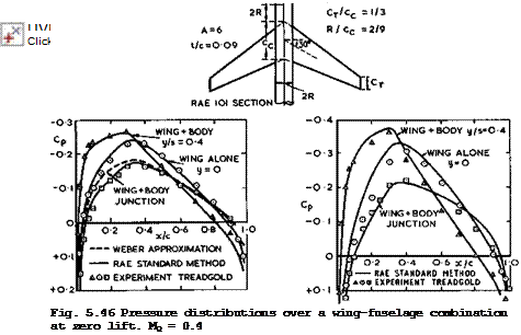
(1970) , and J Bridgewater et al. (1970). Many of these results have not yet been fully analysed, and we present here only a few typical examples, first for symmetrical non-lifting configurations.
Figs. 5.46 and 5.47 show pressure distributions over a wing of moderate sweep (the same as in Fig.4.60) on a fuselage of simple shape at two subcritical Mach numbers from tests by D A Treadgold (1970, unpublished). All the individual terms in (5.26) can be identified in this test. The conditions near midsemispan (y/s = 0.4, triangles) approach those on a corresponding sheared wing (vg). The difference between these curves and those for the centre of the wing alone (y = 0, circles) may be interpreted as representing the kink or reflection effect (vjn) . The remaining difference between the centre curve and those for the wing-body junction (squares) represents the junction interference (vj). v„ in (5.26) may be assumed to be small in the present case. The junction ana reflection effects are of comparable magnitude in this example but of quite a different nature. The results calculated by the RAE Standard Method (using sources along the axis of the fuselage to determine Vj) give an adequate overall representation of the various effects but there are discrepancies in detail where the available evidence is not sufficient to tell whether they are caused by possible uncertainties or inaccuracies in calculating the inviscid flow, or in the compressibility effects, or in leaving out effects of viscosity, or in the experiment itself. The discrepancies are large enough at the centre section at the higher Mach number (Fig. 5.47) to infer that the compressibility factors used are probably not adequate. Also, the pressure along the junction (in Fig. 5.47) should be represented better by Weber’s method, using sources over the surface of the fuselage, than by sources along the axis, although the calculated curve then lies further away from the mea-
![]()
 |
|
The Design of Classical and Swept Aircraft
Fig. 5.47 Pressure distributions over a wing-fuselage combination at zero lift. Mq — 0.8
sured points. Perhaps, this difference may leave room for the effect of viscosity. Obviously, more detailed tests and calculations are needed to get all the physical effects into focus. This holds also for all the further experimental and theoretical results below: only the dominant trends can as yet be discerned. An extension of the RAE Standard Method by Sells’s iteration procedure should offer the best prospects for further advances.
The results in Fig. 5.48 illustrate the large changes in pressure which occur when the junction is approached, first for subcritical flow and then for a freestream Mach number where the flow is evidently supercritical over the wing and includes shockwaves. In this particular case, the shockwave has reached the trailing edge in the junction already at Mq = 0.91. We shall see later how this can be prevented by suitable design.
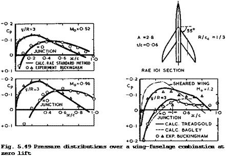
Figs. 5.49 and 5.50 give results for a more highly sweptback wing at three Mach numbers. The flow would have been subcritical over the corresponding infinite sheared wing even at Mq = 1.2 (as indicated in Fig. 4.8), but it is evidently not on this threedimensional wing. In fact, the junction and reflection effects appear to combine to make the flow supercritical near the junction already at some high-subsonic Mach number, with a shockwave at the trailing edge in the junction. Again, the RAE Standard Method gives an overall description of the subcritical flow. At Mq = 1.2 , we can see how much it matters to take account of the reflection effects (Bagley) and to include also disturbances propagated around the fuselage from the other side (Treadgold); the latter reach the junction at the point marked A.
|
The Aerodynamic Design of Aircraft
Fig. 5.50 Pressure distributions over a wing-fuselage combination at zero lift
|
|
|
|
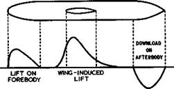
Consider now lifting wing-fuselage combinations where the fuselage is at an angle of incidence ctg and the wing at an angle a. A simplified configuration like that in Fig. 5.51 may help to clarify the basic physical effects that occur. The wing is assumed to pass through a cylindrical part of the fuselage, and this cylindrical part is assumed to be long enough that forces over the forebody and over the afterbody have faded out there and do not affect
|
Fig. 5.51 Lift distribution along a fuselage with a wing in midwing position |
the region of interference with the wing. This interference can then be thought of again as that between a wing and an infinitely-long cylindrical fuselage. As already discussed in connection with Fig. 5.39, the loading over the wing is changed by the presence of the body and, also, the loading is carried across the fuselage, extending from some way upstream of the wing leading edge to some way downstream of the trailing edge. If ов ф 0 , the lengthwise loading along the fuselage is roughly as indicated in Fig. 5.51. The download over the afterbody is shown there to be about equal and opposite to the upload over the forebody. This can only be so in the absence of viscous effects and if the downwash angle induced by the wing trailing vortices over the
afterbody is small enough to be neglected. If the value of oi£ is significant so that the afterbody is situated in a stream with a downward inclination, then the download will be reduced accordingly and the unstable pitching moment will be smaller than on the fuselage alone. In a real case, the three contributing loadings may not be kept neatly apart, as in Fig. 5.51, but it is easy to see how they will merge.
In principle, the loading over a lifting wing-fuselage combination may be determined by a panel method, if suitable lifting elements and a vortex wake are incorporated. Again in principle, Weber’s method can deal with general lifting shapes, using singularities within the wing, as in Fig. 5.40, and continuous compensating source distxnbutions over the surface of the fuselage.
An alternative, much simpler and yet quite accurate, method has been developed by J Weber (1969), where the classical aerofoil equation (4.81) is used within the framework of the RAE Standard Method. The compensating source distribution over the fuselage is determined first and from that the downwash over the wing, as in the example of Fig. 5.39. For a wing of given shape, this down – wash may be interpreted as a change of the mean effective angle of incidence and hence of the sectional lift slope a = CL/ae, to be inserted into (4.81). It then remains to calculate the downwash angle induced by the trailing
vortex sheet which should now include vorticity along the fuselage. It is by no means clear how these vortices continue into the wake, i. e. where the Kutta condition should be fulfilled. Following H Multhopp (1941), we may bypass this awkward question by assuming that the cylindrical part of the fuselage behind the wing is long enough for conditions in a crossflow plane there to be interpreted as those in the Trefftz plane at infinity in the wake. Now, the
trace of the fuselage and of the wing in the Trefftz plane can be transformed into a single horizontal slit, with the trace of the fuselage reduced to a slit along the line of symmetry, which does not disturb a flow normal to the slit representing the transformed wing. Following the classical arguments explained in Section 3.2 (see also Fig. 3.2), we can then work out the potential difference across the slit in the Trefftz plane and from there the spanwise downwash distribution a^(y) over the actual wing. It turns out that the complete loading equation is of the same form as (4.81) and can thus be solved by standard methods. There is now a factor 1 + f(y) multiplying the down – wash integral in (4.81), where f(y) depends only on the geometry of the configuration, i. e. on the shape of the cross section of the fuselage. For the special case of a wing mounted symmetrically on a circular cylinder of radius R, we have
![]()
![]() f (у) = 1/ (y/R)
f (у) = 1/ (y/R)
With the loading known over the whole wing surface, the RAE Standard Method can be applied to calculate the pressure distribution approximately.
The distribution of lift over the body which the wing induces cannot be determined in the same way as the lift on the wing itself. The trailing vortices from the body cancel each other out in the transformed Trefftz plane, which accounts for the fact that the aerofoil equation remains the same as (4.81).
But the integral of the pressure difference across the fuselage can be related to the potential function in the Trefftz plane and this can be used to obtain an approximation for the loading over the fuselage. The lift is usually highest in the junction and decreases towards the axis approximately elliptically. For the overall lift Lg over the cylindrical part of the fuselage, A H Flax (1953) has derived the simple relation
![]()
![]()
![]() (5.28)
(5.28)
when the fuselage itself is aligned with the mainstream (see also A H Flax
(1973) and (1974)).
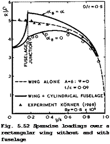
The original method of H Multhopp (1941) has been extended to include the effects of sweep and small aspect ratios by J Weber, D A Kirby & D J Kettle (1951), and this calculation procedure has also been described in the Data Memorandum of the ESDU (Anon (1963)). As explained above, the accuracy of the results can be improved by determining the sectional lift slope of the wing by the method of J Weber (1969). A typical example is shown in Fig. 5.52 for the combination of a relatively long fuselage, as in Fig. 5.46, with an unswept wing. The theoretical results have been obtained by the RAE Standard Method with Weber’s extension, making some allowance for effects of viscosity and of wing thickness appropriate to the wing alone. The experimental results (triangles and circles, which are mean values for aw = 2.9° and 5.8°) have been obtained by H KBrner (1969). There appear to be some additional effects of viscosity in the case of the wing-fuselage combination, as is expected, but these cannot be identified in detail. As before, the RAE Standard Method gives a reasonable description of the overall features.
The example in Fig. 5.52 illustrates also the strong effect on the lo’ading of the inclination of the fuselage. When = 0, the interference reduces the loading everywhere. When otg = a, so that the fuselage is also inclined to the stream, there is a strong crossflow and hence an upwash along the sides of
the fuselage, which hits the wing and increases the lift on it everywhere. For example, if the wing is put in midwing position on a long fuselage of circular cross-section at the same angle of incidence a, then the wing at the junction is at a local angle of incidence of 2a (the velocity at the sides of a circular cylinder being twice that of the oncoming stream). The resulting lift increase is a general feature of all good theories (see e. g. В Maskew (1970)). Fig. 5.52 also shows the elliptical hole in the spanwise loading
 LIVE GRAPH
Click here to view across the fuselage. Here, is must be borne in mind that this is only a fairly crude approximation for the wing-induced lift, defined in principle in Fig. 5.51 but not well defined in many practical cases, and that it rests on the assumption that the Trefftz plane may be placed rather close to the wing where the fuselage is still cylindrical. This difficulty of not knowing how the Kutta condition should be fulfilled applies to all available theories, and so this state of affairs is not altogether satisfactory.
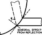
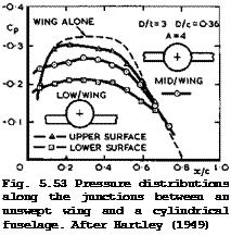
At this point, we must consider in more detail what happens in the junction when the configuration is not symmetrical, as has been implied so far. Already if the wing section is cambered, or if the wing chord is set at an angle to the centreline of the fuselage, then the intersection shapes along the upper and the lower surfaces are not the same, even when the cross-section of the fuselage is circular. As a consequence, the velocity distributions along the junctions differ from one another and also from the value of vj for the corresponding symmetrical configuration. Similarly, deviations from this value of Vj must occur when the wing is not in a symmetrical midwing position. These deviations are usually quite large, as can be seen from the simple but typical example in Fig. 5.53 where both wing and fuselage are at zero angle of incidence. Here, C j = 2 Vj for the symmetrical configuration is the difference between the dashed line and the line through the circles. The changes due to the asymmetry introduced—by the low-wing position are seen to be of the same magnitude, and there is a circulation and hence a lift force acting in the asymmetrical junction. In this not-so-severe case of asymmetry,
the flow did follow the intersection lines. This need not be so in more extreme cases of high – or low-wing positions, and matters are then even more complicated and uncertain (see e. g, D E Hartley (1949)).
 LIVE GRAPH
Click here to view
A practical way of thinking about this effect is to consider again the reflection of the wing in the body wall in the neighbourhood of the junction. There is now, in general, not only a kink in the wing and its reflection in planview, as indicated in Fig. 5.40, but also a kink in frontview, as indicated in Fig. 5.53. The wing has, in effect, acquired an angle of dihedral in that region. The angle of dihedral ф can be defined approximately if the radius of curvature of the fuselage is large enough and if the wing thickness is small enough, so that the reflection in a mean tangential plane to the fuselage may be considered. The velocity components induced by kinked elemental source and vortex strips with dihedral and sweep, in incompressible flow, have been calculated by G G Brebner & L A Wyatt (1970) (see also D KUchemann (1970)). The results are not altogether obvious and illustrate the complicated nature of the flowfield near these kinks of non-planar singularity distributions. To a first approximation, all the additional kink terms turn out to be proportional to the local source and vortex strengths. The outstanding feature of these results is that, at the kink section, a distribution of sources with constant spanwise strength gives rise to a component of downwash in the plane of symmetry» vz » which has the same direction on both sides of the chordal planes representing the wing with dihedral; and a distribution of vortex lines with constant spanwise strength gives rise to a component of downwash which has opposite signs on either side of the chordal planes. That is, part of the down – wash due to sources has a characteristic which we normally associate with a vortex distribution, and part of the downwash due to the vortices has a char
acteristic which we normally associate with a source distribution. In addition, the chordwise velocity increment, vx, due to the vortices has a term proportional to the local vortex strength, which has the same sign above and below the chordal planes, i. e. it is of the form usually associated with a source distribution. Thus the great simplification that linear theory brings to the study of planar wings, namely, the ability to treat thickness and lift effects separately, no longer applies when the wing has a dihedral angle or when it is joined asymmetrically to a fuselage. All these effects are real and strong, and windtunnel tests by G G Brebner (unpublished) on an untapered wing with constant symmetrical aerofoil section and with 45° sweepback and some 30° dihedral have shown that, at and near the centre section, there is indeed an appreciable lift force at zero angle of incidence.
Brebner’s theory has not yet been worked out in more detail and incorporated into the RAE Standard Method, for which it is suitable. These local dihedral und reflection effects matter especially for methods using panel elements on the surface since such elements are then themselves joined at all kinds of angles along the junction, even when the wing is in the midwing position, when the effective angle ф is near 45° for two panels adjoining the junction.
The known analytical nature of the reflection terms is such that the boundary conditions in the junction are violated unless both source and vortex distributions have the correct behaviour and the source distribution, in particular, tends to zero in the junction in a certain manner so that the relevant kink terms vanish. It appears that only A Roberts & К Rundle (1972) have considered these matters and that the region of the junction is ignored in other panel methods, regardless of the fact that the interference effects to be computed are largest in the junction. We have already seen from the relatively simple example in Fig. 5.43 that this may lead to serious errors. Until these matters have been clarified and taken into account, any claims, which are often made, that a computer program could deal with wing-fuselage or even more complicated configurations of arbitrary shape, cannot be accepted: the essential part of the problem has not yet been tackled.
The effects of significant asymmetries in wing-fuselage junctions are usually detrimental. Effects of viscosity tend to make them worse: if the angle between the two walls is very obtuse and the junction too shallow, the air may flow across the intersection line and produce unwanted suction peaks or flow separations; if the angle is too acute, the viscous region with its crossflows and concentrations of vorticity may have an even stronger effect and again lead to flow separations, especially when this happens in the adverse pressure gradient near the trailing edge of the wing. For these reasons, fairings are put into the wing-fuselage junction in many actual aircraft in such a way that the walls meet nearly at right angles or are joined by gently rounded panels. The design of these fairings is mostly empirical and crude (but see R Legendre
(1973) ). What is needed is a good design method which can deal with arbitrary cross-sections of non-circular shape, for which an extension of Sells’s iteration method of Weber’s theory would be well suited.
We turn now to the question of how wing-fuselage combinations may be designed, following the general principles already discussed in Section 5.3. In addition to the various means for designing wings described there, shaping the fuselage and especially the junction with the wing is obviously a powerful design tool. This has been recognised for a long time, and farfield approaches have been used to deal with wing-fuselage combinations and other multi-body shapes. Area and equivalence rules have been developed by F Keune & К Oswa – titsch (1952) and (1956), F Keune & W Schmidt (1956), К Oswatitsch (1957), and applied with some success by G Drougge (1957). To shape the combined crosssectional area of wing and fuselage like those of a body of revolution which gives in theory the lowest wavedrag due to volume at near-sonic speeds, has also been proposed by R T Whitcomb (1952) and by W T Lord (1953). Such shapes usually bring some improvement over plain wings and fuselages, but in Whitcomb’s tests, for example, the drag rise occurred at a Mach Number which was significantly lower than the critical Mach Number of the corresponding infinite sheared wing, i. e. straight and fully-swept isobars, as in Fig. 5.1(b), had not been achieved. To eliminate the arbitrariness inherent in area rules and to ensure that the design flow is physically realistic and efficient requires a nearfield approach to the problem. This has been developed by D KUchemann (1947) and (1957), Anon (1949), J A Bagley (1955), (1956), (1957) and (1961), and R C Lock (1963). ‘ A successful body-contouring method has also been developed by J В McDevitt & W M Haire (1954), and C L Bore (1971) has summarised available design methods and criteria.
If the nearfield approach is used to design for a particular isobar pattern over the wing (Fig. 5.1) by exploiting the interference between wing and fuselage, it is advisable to begin by finding a shape of the intersection line between the two bodies along which the required pressure distribution is obtained, because the interference is strongest in the junction: the undesirable distortions are largest there and hence also are the benefits to be obtained when they are eliminated by suitable shaping. If the flow in the junction is right, then the flow is usually nearly right everywhere else on the wing.
In many practical cases, the resulting intersection shape has a characteristic feature: the designed fuselage acquires an indentation, it is waisted.
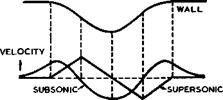
This is a consequence of the fact that the main distortions to be eliminated also have a characteristic feature. This can be explained as follows: when a cylindrical fuselage is combined with a swept wing, the main distortion in the junction arises from the central kink or reflection term vq in (5.26). When the wing is sweptback, vq generally reduces the velocity below the sheared-wing value vg over the front part of the aerofoil and increases them over the rear part, the trend being the same for both thickness and lift effects. Now, if the junction is to be shaped so that vj compensates for Vq, then vj must be positive over the front part and negative over the rear part. As can be seen from the central sketch in Fig. 5.54, a curved wall with an indentation will do just that, whether the mainstream is subsonic or supersonic. Thus designed fuselages will always be waisted and will differ only in detail. Typical shapes for actual designs to compensate for the kink effects caused by thickness only are shown in Fig. 5.55 for a wing of moderate sweep at a subsonic Mach Number and also for a more highly-swept wing at a low-supersonic Mach Number. We note that the indentations needed are quite sizeable. This is one of the reasons why conservative aircraft designers have so far not applied this powerful design tool.
|
Fig. 5.54 Velocity distributions along a curved wall |
Fig. 5.55 Typical shapes of wing-fuselage intersections to compensate for the centre effect due to thickness. Left: for a wing with 9 = 35° and t/c = 0.1 at Mq = 0.85. Right: for a wing with 9 = 55° and t/c = 0.06 at Mq = 1.2 . Dashed lines: cylindrical fuselage. RAE 101 section
For lifting configurations, the specification of sheared-wing pressure distributions in both junctions will, in general, lead to different intersection shapes along the upper and lower surfaces, which do not meet at the trailing edge (see R C Lock, (1963)). A horizontal ledge is then left along the fuselage downstream of the trailing edge of the wing. Although the effects of such a discontinuity have not been fully explored, they are not necessarily harmful.
The simplest method of designing such shapes is one where the fuselage is regarded as a quasi—cylindrical shape. All the examples described below have been designed in this way. But it is obviously too restrictive to design the fuselage as a waisted body of revolution: The isobar pattern across the body
should also be defined, and this would generally lead to non-circular crosssections and require an extension of Weber’s theory and also the establishment of suitable design criteria for isobar patterns across the fuselage.
Apart from proposing that isobars may be continued at a high angle of sweep
across the fuselage, leading to a bulge on top of it, neither of these prob
lems has as yet received much attention. What to do in the important case of supercritical mixed flows involving shockwaves is not yet clear. Obviously, the physics of these flows has to be clarified first – computer programs are not likely to produce the design concepts needed without further thought.
As far as the isobar pattern over the wing is concerned, fuselage shaping allows a much wider ohoioe than the patterns shown in Fig. 5.1. An extreme possibility has been proposed by J A Bagley (1955): to shape the junction so
that Cpj = 0 along it, i. e. vj in (5.26) is to cancel all the other con
tributory velocity increments. One such shape is shown in Fig. 5.56 for a highly-swept wing at Mq = 1.1. The pressure drag is then zero in the junction itself, but whether a reduction of the overall drag can be achieved depends on the flow over the rest of the wing. J E Rossiter (1957) has calculated such flows and found that, for the simple case of unswept wings of constant chord at supersonic speeds, the overall change in drag is exactly zero if small-perturbation assumptions of linearised theory are applied and if the wingspan is large enough so that the Mach line from the apex of the wing root runs across the whole wing and does not intersect the wing tip. Drag increases over the outer part of the wing then cancel exactly the drag reductions in the region of the junction. An overall drag reduction may result if
|
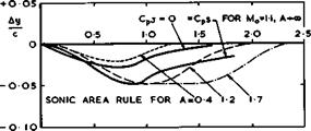
Fig. 5.56 Some junction shapes according to different design methods. Swept – back wing with biconvex section, 9 = 60°, t/c = 0.05, on circular-cylindrical body with d/c =0.3 |
the wingspan is cut down or if it is assumed that the disturbances from the junction are attenuated with distance from the junction. When the wing is swept, isobars will form closed loops and thus lose sweep somewhere so that the critical Mach number may be decreased just outboard of the junction, even though the pressure drag in the junction may be lower in such a design. Until these matters are clarified further it seems safer to design for isobar patterns as in Fig. 5.1 (b) to (d). The junction shape to give fully-swept isobars over the wing (strictly to give Cpj = CpS) is also shown in the example of Fig. 5.56; this requires a much deeper waist. The junction shapes obtained by the sonic area rule for different aspect ratios of the wing are also indicated in Fig. 5.56. These differ substantially from one another and also from the shapes calculated to give specified pressure distributions.
From a nearfield approach, some of the area-rule shapes may happen to have pressure distributions to give some beneficial effect, but it is difficult to see on physical grounds why they should always do so.
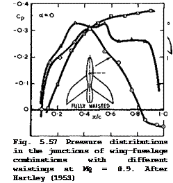
Next, we may briefly consider some experimental evidence to see how effective the nearfield design methods are, first for non-lifting eon figurations. In Fig. 5.57, we repeat one of the pressure distributions (squares) in the junction between a moderately sweptwing and a cylindrical fuselage from Fig. 5.48. This flow is strongly supercritical, and we find from the results in Fig. 5.57 (circles) that this can be converted into a shockless subcritical flow with full pressure recovery towards the trailing edge by a fully-waisted fuselage.
If the bulge at the rear is removed, the resulting half-waisted fuselage (triangles) is naturally less effective: the isobars are likely to remain unswept over the rear wing near the root and the flow is still supersonic locally (the critical pressure coefficient Cp* = -0.19 for 9 = 0° at Mo =
0.9 , whereas Cp* = -0.48 for isobars which are fully swept at 9 = 40° ), with a shockwave just upstream of the trailing edge. This confirms what we have already noted in Section 5.4 in connection with Fig. 5.27, namely, that rear bodies near the trailing edge may be effective means for eliminating rear shockwaves. This was again confirmed by flight tests by D R Andrews et al. (1956) on the Hawker Hunter aircraft, for which J A Bagley (1954) had designed a bulge over the rear of the fuselage to increase the pressure significantly over the rear half of the wing root. At zero lift, the whole of the Cd(Mq)-curve was shifted roughly to the right by about AMq = 0.02 when the bulge was added. In practical terms, this means that the Hunter aircraft with bulge had about the same drag curve as the F-86 aircraft, which has a wing with about 5° more sweep (45° instead of 40°) and with about 15% thinner sections (t/c = 0.07 instead of 0.085).
 |
 |
The Design of Classical and Swept Aircraft
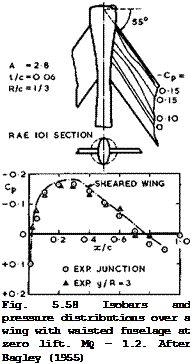
An example of a more highly-swept wing at low-supersonic speed is shown in Fig. 5.58. The results are to be compared with those in Fig. 5.50 for this
 LIVE GRAPH
Click here to view
The Aerodynamic Design of Aircraft
![]()
 |
|
wing with a cylindrical body, where the flow appears to be supercritical near the wing root. The waisted body in Fig. 5.58 was designed by J A Bagley (1955) to give a pressure distribution in the junction like that over the corresponding sheared wing, with the aim of obtaining fully-swept isobars. The results demonstrate that this has been achieved quite satisfactorily. Altogether, we can conclude that the nearfield design concept of straight isobars, based on subcritical sheared-wing pressures, appears to be realistic and successful also for wing-fuselage combinations.
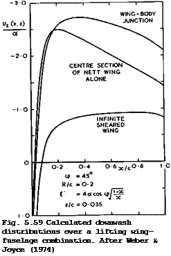
The methods described above can, in principle, also be applied to lifting configurations. The interference by the fuselage strongly affects the shape of the wing if this is to carry a prescribed load distribution, as has already been shown in Fig. 5.39 for the case of an unswept wing with flat-plate loading. Fig. 5.59 gives a counterpart of this for the case when the wing is swept. The downwash v (x) has been calculated by J Weber & G Joyce (1974) on the wing surface, off the chordal plane (strictly, at a constant value z/c ■ 0.035) so as to avoid the infinite downwash at the kink of a thin wing. From the values of vz(x) , cambered and twisted wing sections can be derived to give the same flat-plate loading all along the span. The shape of such a section at the centre of a wing alone will obviously be quite different from that in the wing-body junction. Conversely, a wing of given shape will support quite different loadings in the two cases. In either case, threedimensional effects cause very large deviations from the properties of an infinite sheared wing: the effects of the reflection in the body side and of the fuselage interference are considerable.
There is very little experimental evidence to check design methods for lifting
Previous Page
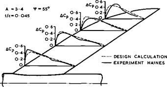
configurations. We refer here to one of the series of wings with 55° sweep, with camber and twist, which was designed by R C Lock (1963) to have the same chordwise loading all along the span and tested by A В Haines (unpublished) . Linearised theory was used, with some allowance for non-linear effects near the leading and trailing edges. The theoretical and experimental results for the design Mach number Mq = 1.19 are shown in Fig. 5.60. The agreement is satisfactory; the small discrepancies that do occur cannot yet be interpreted
|
Fig. 5.60 Loadings over a sweptback wing at Mq = 1.19, = 0.25 (design). After Lock (1963) and Haines ‘ |
in detail. Nevertheless, the possibility of achieving efficient lifting designs by nearfield methods has been demonstrated up to low-supersonic Mach numbers, and we may conclude that the swept wing-fuselage combination is indeed the natural aerodynamic shape for this range of cruising speeds.


