CHANGE OF FLIGHT-PATH ANGLE
The phugoid makes its presence known not only in the form of transient perturbations from a steady state, but also in maneuvers, as illustrated in Sec. 10.3. We saw there for example that in changing from level to climbing flight by opening the throttle (Fig. 10.7) there results a protracted, weakly damped approach to the new state that would take some 10 min to complete. Transitions from one value of у to another are obviously not made in this manner, and the pilot suppresses the oscillation in this case as well. Provided that the correct в is known for the climb condition, the same technique as discussed above would work, i. e. proportional control operating on pitch – attitude error. We illustrate an alternative concept that does not require any knowledge of the final correct pitch attitude, but that uses speed error alone. Figure 11.3a shows the system. In this case it is found that proportional control is not adequate—it serves mainly to shorten the period of the oscillation, but has little elfect on the damping. To improve damping needs rate control, so the control law used is
|
|||
|
|
||
|
|||
|

where the signs of the gains have been chosen to give the required corrections.
Just as in the case of в feedback above, the characteristic equation can he obtained from the approximate transfer function, in this case Gys. It is given by (10.2,15a), i. e. with the same approximations as used above,
D(s)
where D(s) is given by (11.2,6) and (11.2,8) and
N3(s) = mps + m0 % = 2f*GDGmJCmx
mo = GwGLCmJCmx (11.2,14)
The characteristic equation [cf. (11.2,5)] is
D(s) + (Jq + kzs)N3(s) = 0
which becomes
(c2 + mjlc^s* – f (tq + тД + m0kz)s + (c0 + kym^ = 0 (11.2,15)
The new characteristic equation is again second order, being the sum of the original one and additional terms. When the signs of the quantities in (11.2,14) are taken into account, the modifications to the three original coffiecients can be summarized thus
c2: increased by amount proportional to kz
Cj: increased by amounts proportional to Aq and kz
c0: increased by an amount proportional to Aq
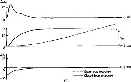
Since there are two free constants, k1 and kz, we can analytically satisfy two conditions by means of (11.2,15)—one on the period, and one on the damping of the closed-loop system. This procedure is fairly obvious, and is not elaborated on here. The values of the constants finally chosen have to be constrained of course by practical considerations related to sensor and control hardware limitations. Finally, the approximate analysis has to be verified with the complete system of equations. As an example, Fig. 11.3 shows the response to a step input of thrust obtained using analogue computation of the full system of equations. The constants used were
Aq = .30 rad/unit; k2 = 1000 rad/unit
The first corresponds to a deflection of.172° per 1 % change in speed, and the second to 25.3° per g of forward acceleration. The airplane and flight condition of the figure are the same as those for Fig. 10.7. The dashed lines show the beginning of the phugoid response that would exist without feedback. This would take about 10 min to decay. The solid lines show the response with feedback, and we see that for all practical purposes the transition is completed smoothly and rapidly—within about 15 sec. There is a small overshoot in y, and small errors in AV and AS that die out rather slowly. This feature could be eliminated at the cost of some additional complexity by introducing some integral control. The elevator angle variation required to accomplish the transition is seen to consist of an initial step (up-elevator) followed by a gradual reduction of the deflection. The conditions near t = 0 are, of course, somewhat artificial because of the step input used.
A gradual thrust increase would have resulted in a gradual deflection of the elevator. It should be noted that the error in AF, the primary quantity sensed, is indeed kept quite small. The role of Да is worth commenting on. At the scale of the figure, there is practically no a change in the open-loop case within the time span shown. The “pulse” in a in the closed-loop case clearly has the effect of producing a corresponding pulse in lift that rotates the velocity vector through the required angle.
Finally, it should be observed that in theory a human pilot has all the state information that we have assumed was available. V and T could be obtained from an airspeed indicator, and additional information about T can be felt as an inertia force (a “seat-of-the-pants” input). An autopilot could readily have AF supplied in electronic form by a conventional transducer, but would be somewhat more troublesome. The two principal alternatives would be differentiation of F, or an acceleration signal from an inertial platform.


