CHARACTERISTICS AT HIGH ANGLES OF SIMPLE SWEPT WINGS
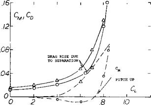
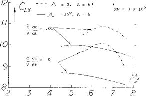
Typical characteristics of simple swept wings (1) with A = 35 and 45° as a function of angle of attack are given on figure 1. Although the change of lift as stall is approached and exceeded is generally gradual, the drag rise is very steep and the pitching moment curve becomes positive. These moment and drag characteristics tend to increase the wing angle of attack which is destabilizing and, of course, undesirable. Thus, modifications are required to eliminate or reduce the pitch up moment developed by swept wings. The stall characteristics discussed above are caused by the loss of lift at the wing tips which are located aft of the aerodynamic center. This lift loss causes a pitch up moment and is aggravated by a vortex formed on the leading edge of the wing that flows span wise inboard from the tip. With increasing angle of attack this vortex is shed further inboard from the tip causing an effective loss of aspect ratio with a sharp increase in drag as shown on figure 1. Thus it is also noted that at the stall angle the drag increases sharply reflecting the increase in separation and the decrease of effective aspect ratio.
(1) Stall characteristics of plain swept wings:
a) Hunton Section Characteristics A = 45°, A = 6, NACA TN 3008.
b) Goodman & Brewer. Low Speed, Aspect Ratio & Sweep Characteristics. NACA TN 1669.
c) Turner, Effects of Sweep on CLX, A = 4, NACA TN 3468
d) Platt and Brooks, Effects of A – 0, 35 and 45 at Transonic Speeds, NACA RM L54L31b
e) Hopkins, Effects of Sweep Forward and Back, A = -40 to +45°, A = 2.8 to 6.8, NACA TN 2284.
f) Kuhn and Wiggins, 45° Swept Wing at A = 2,4 & 6 with fuselage, NACA RM L52A29.
g) Pursen, Swept & Yawed Wings of Various Planforms, NACA TN 2445.
h) Haines, Tests of 50° Swept Wings, ARC R&M 3043.

 Although the variation of the lift coefficient curve with angle is gradual after the stall is encountered, the usable value of lift coefficient is much lower than C, x because of the pitch up moment. This problem increases with speed as high speed buffet is encountered. Thus a relatively low useful value of lift are obtained at the higher operating Mach numbers. For these reasons when considering swept wing aircraft the stall characteristics encountered at both ends of the flight range are critical.
|
|
|
Figure 1. Typical characteristics of swept wing operating at high angles of attack. |
MAXIMUM LIFT – SWEPT WINGS. As discussed in the last chapter the characteristics of airfoils installed on a swept wing, in accordance with the simple sweep theory, depend on the flow velocity normal to the effective wing chord line. The section ordinates normal to this chord line determine the pressure distribution on the airfoil. Figure 3 in Chapter XV shows that the pressure distribution on the airfoil is independent of the sweep angle, provided the velocity chosen is parallel to the chord line. Thus for a swept wing
(i)
where Cps is the pressure coefficient of a two dimensional section. Since the shape of the pressure distribution curve of an airfoil determines the maximum lift coefficient we can, therefore, expect that
cix =CLxs cos2-A. (2)
where C^Xs is the maximum lift coefficient of the section in two dimensional flow. Thus for a 45° swept wing, the maximum lift would be expected to be half that of an equivalent straight wing.
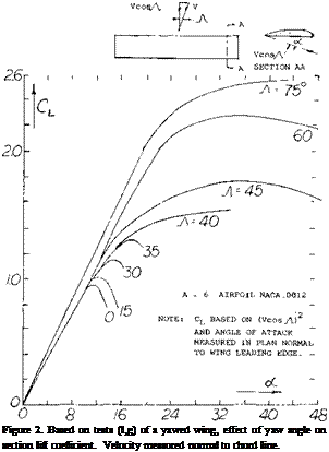
Tests (l, g) of a rectangular wing of A = 6 at yaw angles of 0 to 75° show, in figure 2 that C^xs actually increases with sweep or yaw angle rather than remaining constant as would be indicated by equation 2. At an equivalent sweep angle of 45° the level of CLXS shown is nearly twice that expected by equation 2.
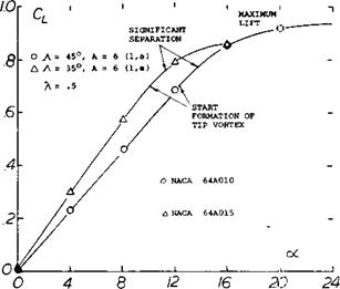
Further experimental confirmation of the maximum lift characteristics of swept wings (1) tested as complete wings and on a reflection plane shows an increase of with A. These data, figure 3, show that both angle of sweep and aspect ratio are important in determining the level of maximum lift.
![]()
 b) SECTION DRAG SHOWING SUDDEN INCREASE AT Cr. = 0.56.
FLOW UNSTABLE
|
|
|
: 6.8 : 5.8 : 4.2 |
|
A = 6 (1, a ) |
|
NO TWIST NACA 64A006 TWIST NACA S.4A810 NACA 65A00C |
|
Figure 3. Sweep angle and aspect ratio effects on CLx for simple swept wings. |
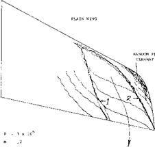
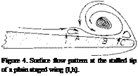
WING TIP FLOW. In a manner similar to that of straight wings, a flow of air (including some boundary-layer material) around the lateral edge, is caused by the pressure difference between the lower and upper side of the wing. At the same time the boundary-layer material as in figure 4 moves along the upper side toward the wing tip. As illustrated in figure 4, the two streams meet and combine, thus forming a strong trailing vortex. It should be noted that at (A) there is a weak stagnation point (causing a small secondary vortex), while at (B) a pressure minimum is obtained, thus indicating location and path of the vortex as in figure 4. Another weak vortex is formed at C.
|
|
With increasing angle of attack, the main vortex grows in diameter (if that word can be used) and it moves farther inboard, as far as one tip chord, for example, at cC = 15° for the wing as in figure 4. The lines (1) and (2) in the illustration roughly indicate the boundaries of the main vortex. Since the flow is a fully separated area at (3), the forward corner of the wing may just as well be cut off as shown.
 |
A = 6 swept wing
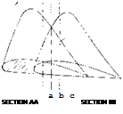
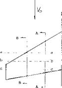
 on the wing. Consider for instance the pressure distribution of sections AA and BB shown on figure 6. At point (a) on section AA it is noted that the negative pressure remains lower in the chordwise direction than spanwise until point (b) is reached. Thus, the flow will move along the chord as shown. However, when point (b) is reached the pressure is lower outboard at (c) on section BB than at (c!). This causes the flow to move in the spanwise direction.
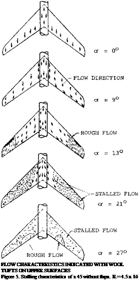
Since the spanwise flow of the boundary lave]’ prevents, separation on the inboard sections of the wing unstable flow first starts at the tip of the wing and is a function of the airfoil section type, leading edge radius and Reynolds number. This tip separation spreads to the leading edge at the tip and continues to move inboard with increasing angle of attack as shown on figure 5. With a further increase of angle the vortex separates from the leading edge inboard of the tip and flows chordwise. This leaves the tip of the wing completely stalled. The span station where the separation takes place continues to move inboard with increasing angle of attack.
|
|
Figure 6. Section pressure distribution for swept back wings as influencing boundary layer flow.
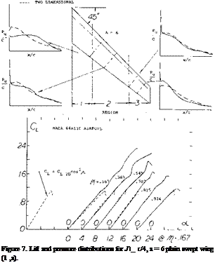
The data (l, a) given in figure 7 shows that the local variation of CL with oc has the same slope in the middle of the wing semi-span as would be predicted based on airfoil section tests. The lift, however, continues to increase with angle to much higher values than predicted due to the boundary layer transport. The increase of CLX compared to the two dimensional data is much higher inboard than near the tip. At the tip CLX nearly equals the two dimensional value corrected according to equation (2). This illustrates that without the boundary layer transport effect the maximum lift would be lower than that of straight wings.
![]()
The actual flow pattern in the boundary layer and, therefore, the degree of improvement of section CLX depends on the geometry of the wing including aspect ratio, sweep angle, taper ratio, wash out and section type. The data given on figure 7 illustrates the variation of the local sectional lift coefficient as a function of span location. The variation of the corresponding two dimensional section data corrected for sweep according to the cosine principle is shown for comparison.
(2) Theoretical Methods:
a) Anderson, Determination of the Characteristics of Tapered Wings, NACA TR 572.
b) Kuchemann, Loading Straight & Swept Wings, ARC 15633, R&M 2935.
c) Lamar, Multhrops Approach for Predicting Lifting Pressures Subsonic Flow, NASA TN D-4427.
d) DeYoung, Span Loading Arbitrary Planforms Subsonic, NACA TR 921.
e) Blackwell, Load Distributions Swept Wings with Pylon Plates, Subsonic, NASA TN D-5335.
f) Van Dorm, Companion of Theoretical Methods Swept Wings, NACA TN 1476.
g) Papas, Leading-Edge Swept Wings at Low Speeds, JAS Vol. 21, 10’54
![]() INFLUENCE OF SECTION STALL. In Chapter IV it was shown that the chordwise location of the flap separation has an important influence on the type and magnitude of stall. For instance, the flow can separate at the leading edge as a short or long bubble or separation can start at the trailing edge and increase in intensity until it: covers the entire airfoil. The variation of lift with angle of attack and the type of stall are shown to be dependent on where separation takes place on the airfoil. In the case of swept wings, the stall is also effected by the chordwise location of separation.
INFLUENCE OF SECTION STALL. In Chapter IV it was shown that the chordwise location of the flap separation has an important influence on the type and magnitude of stall. For instance, the flow can separate at the leading edge as a short or long bubble or separation can start at the trailing edge and increase in intensity until it: covers the entire airfoil. The variation of lift with angle of attack and the type of stall are shown to be dependent on where separation takes place on the airfoil. In the case of swept wings, the stall is also effected by the chordwise location of separation.
In the case of swept wing the spanwise boundary layer transport does not influence the type of stall on the outboard sections of the wings from that expected, in two dimensional flow corrected according to the cosine principle, figure 7. However, on the inboard sections the effects of the boundary layer improve conditions at the trailing edge sufficiently so the stall generally starts by leading edge separation. This is illustrated in figure 7. Outboard on the wing the suction in boundary layer also protects the trailing edge from separation, thus stall takes place first at the leading edge. A vortex is formed at the leading edge starting outboard on the wing in a manner similar to the vortex formed in conjunction with sharp leading edge stall discussed in Chapter IV. Inspite of the leading edge separation where a sharp stall is expected the stall of the swept wing remains gradual with increasing angle of attack.
It has been shown (2,b) that a swept wing can be considered into three regions as shown on figure 7. In the center section panel region the chordwise loading due to incidence can be represented
Co ~ [(1 – X)/x ]n (3)
where x is the chordwise station being considered and n = 1/2 as in two dimensional flow. In this region the local slope of the lift curve is
dCL/do£ -2F cos-A (4)
At the region toward the fuselage the chordwise loading varies according to equation with n equal to 1/2 at the edge of region two to
n = 2 (1 – 2Л/тГ) (at root)
at the wing root. The flow on the wing near the root is thus equivalent to section operating in a negatively cambered airflow. This leads to a new slope of the lift curve
(5)
On the other hand in the region toward the tip the chordwise loading n varies from 1/2 at the edge of region two to
n = 2 (1 + 2А/тг) (at tip)
The above value of n lead to the equation dCL /doC =
2 A (1 + 2 A. Irf) (at the tip) (6)
Thus, in contrast to the root the tip sections operate in a positively cambered flow. This effectively reduces the camber of the section and tends to lower the CLmAX.
Unfortunately, the effect of the boundary layer flow is much stronger than the flow curvature induced at the root and tip of the wing in modifying the section maximum lift characteristics. In the middle sections of the wing panel however, the characteristics of two dimensional sections are a useful guide to determining the lower value of the section CLy especially when leading edge stalling is to be encountered, Chapter IV.
ASPECT RATIO. The effect of the longer panels of high aspect ratio wings is to increase the flow of the boundary layer material in the outboard direction. This increased flow improves the effective boundary layer control at the inboard sections of the wing with a higher section maximum lift coefficient. As a consequence, the higher aspect ratio wings have an increased level of CLX as shown on figure 3.
Although an increase in is obtained with higher
aspect ratio swept wings, tip stalling can take place at a lower angle of attack or operating CL. Thus, the effective or usable maximum lift of higher aspect ratio plane wings is lower. The operating CL of the wing where stalling takes place can be identified by the sharp increase in drag or where CD exceeds the value (figure 1)
Co =CLS I-Іґ ARe (7)
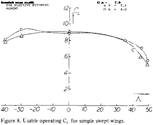
A second way, other than actually measuring the individual section pressure distribution, of finding the onset of tip stalling is a break in the moment curve in the positive direction as shown on figure 1. Based on remaining below an operating where stall takes place, simple swept wings have a lower usable value of with increasing aspect ratio and also sweep angle. This is shown from the limited data given on figure 8.
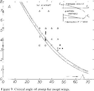
 CRITICAL ANGLE OF SWEEP. In considering the usable operating CL of swept wing, tip stalling is generally the major factor as this leads to the unstable pitch up moment. The combination of aspect ratio and angle of sweep influence the stall and thus the moment.
Thus, for any aspect ratio an angle of sweep can be identified above which a pitch up moment wC be encountered. Based on experimental data (3) the range of aspect ratio and sweep angle for a stable pitching moment curve was established, figure 9.
|
DATA FROM (5, b)
|
(3) Aspect Ratio Effects:
a) Turner, Sweep and Aspect Ratio Effects on CLx, NACA TN 3468.
b) Also (l, a) (1 ,e) (l, g).
For a given wing aspect ratio the critical angle of sweep can thus be determined from the data of figure 9. The curve of critical angle of sweep shows that smaller angles must be used with the higher aspect ratio wings. This is caused by the increase of boundary layer flow which increases the section CLX in a greater proportion inboard than at the tip. Typical swept wing airliners have aspect ratios in the range of 7 to 8. Based on this aspect ratio the permissible angle of sweep given on figure 9 would be around 20°. Since an angle of yaw must be considered of at least 10°, say during a sharp turn, we are therefore left with a permissible sweep angle of only 10°. Modern airliners, for instance the 7X7 series, DC-X types, and fighter aircraft have sweep angles from 25 to 40 plus degrees. Thus, the simple swept wing must be modified for satisfactory operation.
|
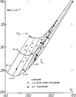
Figure 10. Drag characteristics of a typical jet transport airplane as a function of speed, wing loading and stall ratio (4). |
DRAG AT MAXIMUM LIFT. For a typical swept wing airplane as the ratio of flight speed to the stall decreases, the drag also decreases (4) reaching a minimum at V0 /Vs = 1.3, figure 10. With a further decrease of speed, the drag then increases due to the increase of separation as stall is approached. This increase in drag with decreasing speed causes a speed instability condition that results in a loss of speed and lift unless corrective measures are used, such as a rapid increase of power. When landing in poor weather, the pitch up moment in combination with a smooth gradual stall and drag increase can produce a disaster, especially if the engine response time is low.
 0 8/6 24-
LONGITUDINAL STABILITY. The pitch up moment due to stalling at the tip of a swept wing will result in an unstable aircraft. Thus, as noted in Chapter XI, instead of returning to a lower angle of attack due to a disturbance as with a stable configuration, the angle will become larger increasing the stall. For airplanes operating in the take off and landing range the wing designer has the choice of many different combinations of high lift devices to develop a stable configuration as noted in the section “Design for High CLX ”. To develop a wing with a negative pitching moment in those combinations of A and A exceeding the critical angle of sweep, figure 9, the load distribution must be changed so the inboard sections stall first. As noted later in this chapter and (5), the shifting in load to the inboard sections is impossible with some very high sweep angles and aspect ratio combinations. However, improvements of usable operating lift coefficients of swept wings can still be achieved. This can be done with leading edge extensions, slots and in some cases fences.
(4) Fischel, Low Speed Operation of Jet Transports, NASA M 3-1-59H.
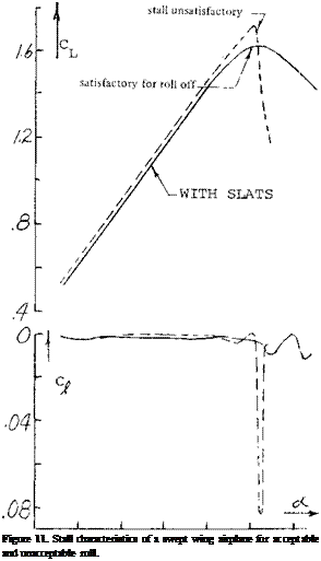
LATERAL STABILITY. Separation at the wing tips and the associated stall is especially undesirable from lateral stability considerations. For instance, if the stall is especially sharp a small change in angle of attack on either wing of an aircraft can cause stall with an associate sharp roll off (6,a). This, as in straight taper wing aircraft, results in unsatisfactory flying qualities. Shown in figure 11 is the variation of lift for a wing with A =35° that in unsatisfactory flying qualities. By using leading edge modification fences the shape of the curve was made more rounded and satisfactory lateral stability characteristics were obtained. Separation at the wing tip also causes the ailerons to become ineffective. In fact, it is noted that several transport aircraft have two pairs of ailerons, one at about 1/2 span, figure 35.
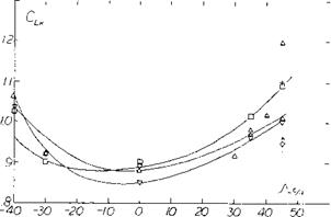
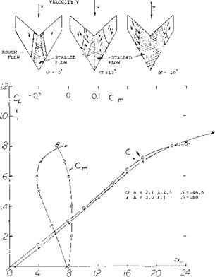
STALL OF SWEPT FORWARD WINGS. As shown in Chapter XV, figure 8 swept forward wings stall near their center sections first, (l, g). This characteristic is desirable from control considerations as the outboard sections are free from separation and the lateral control devices remain effective. Thus, it can be expected that lateral stability and control will be retained with aircraft equipped with swept forward wings. It can also be hoped that the early flow separation, such as is shown on figure 12, will give the pilot a clear warning and provide a pitch down moment by the way of reduced downwash at the horizontal tail surface.
Although the stall of swept forward wing occurs first on the inboard station the unstable pitch up moment is still encountered after the wing sweep angle and aspect ratio exceeds the critical value shown on figure 9. A comparison of the moment curves for swept forward wing with A = 46.6° and 60° given on figure 12 confirms this. The separated flow encountered inboard with swept forward wings will also lead to buffet problems, especially at high speeds. The loading about the wings elastic axis also can possibly lead to structural problems, as the wing will tend to twist up in angles which could lead to aeroelastic problems.
(5) Elimination of Pitch-Up Swept Wings:
a) Weil, Design Studies, NACA RM L53123c.
b) Furlong Summary of the Low-Speed Longitudinal Characteristics of Swept Wings, NACA TR 1339.
(6) Lateral Characteristics of Sweep Wings near Stall:
a) Anderson, Roll-off in Low-speed Stalls on a 35 Swept Wing, also fences, NACA RM A5 3G22.
b) Goodson, Ailerons on Variation of Swept Wings, NACA RM L55L20.
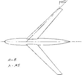
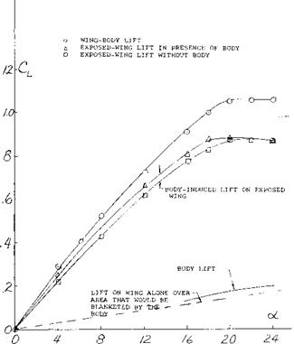
FUSELAGE INTERFERENCE. Due to the increased wing loading of high speed swept wing airplanes the fuselage is often much larger in relation to the wing than some of the slower aircraft. Therefore, the fuselage interaction with the wings becomes an important factor in its effect on load distribution, CL* , flow separation and buffet. At low Mach numbers, (7,a), during takeoff and landing the body adds to the lift in terms of the lift produced by itself and that induced on the wing. The induced lift disappears at CLy but the body lift can increase the maximum by as much as 15% for the zero flapped condition, figure 13. The actual value of L CLX will depend on the body size and the sweep angle, since the sweep angle will determine the angle at stall and the body lift will increase with an increase of angle of attack. At the low speed condition the body has only a small effect on the wing load distribution, especially near stall (7,a).
The overall effects of the fuselage on the lift coefficient where the pitch up moment becomes positive are small (7,b) even with large changes in shape and wing location. Also, changes in fuselage shape and wing location appeared to have little effect on the variation of pitch up moment as the stall is approached. The main influence of such changes on the stability of the aircraft was in yaw as discussed in Chapter XII.
|
FREE STREAM
Figure 12. Swept forward wing lift, moment and stalling characteristics (l, g). |
|
|
|
Figure 13. Division of wing and body lift. |
The fuselage shape and contour at the wing junction has a large influence on the level of usable lift coefficients of a swept wing operating at high Mach numbers. Tests have indicated that with proper modification of the wing juncture, using the methods of (7,c, d) important improvements in pitching moment characteristics, drag and slope of the lift curve can be obtained at high speeds. The largest effects of the change in contour occur at Mach numbers above the critical.
DYNAMIC STALL. In Chapter IV it was shown that the maximum lift of straight wings is influenced by th e rate of change of the angle of attack. Tests (8) indicate that the rate of change of angle of attack also increases CLX – for swept wings. For ~A~- 35° the increase of CLX is larger than for a corresponding straight wing, figure 14. The hysteresis loop developed by straight wings, figure 28, Chapter IV, would also apply for swept wing.
|
|
|
Figure 14. Dynamic stall effects for swept wings. |
PREDICTION OF SWEPT WING STALL. In the design and analysis of swept back wings it is necessary to predict the wing operating CL at which stall takes place. Such procedures are needed to find the conditions where wing section stall may induce a pitch up moment and the effects of wing modification used to delay stall. There are several methods of analysis (2,a, c,d, e) that have been developed for finding the load distribution of wings as a function of planform, twist, section camber and operating conditions. These theoretical methods are based on span loading and lifting surface theories and predict the results with good accuracy at conditions below CLX.. Thus, for instance (l, d) can be used to calculate the load distribution variation as a function of operating CL for any swept back wing. If many calculations are required high speed computing machines are used with (l, c) or (l, e).
(7) Fuselage Interference:
a) Martina, Body Effects on Spanwise Load, NACA TN 3730.
b) King, Effects of Cross-Section Shape and Wing Height,
NACA RM L55J25.
c) Kudemann, Design of Wing Function for Swept Wing at
High Mach Numbers, RAE 2219.
d) Weber, Design of Wing Function, cont., Addendum RAE
2219.
e) McDevitt, Body-contouring at Root Sweptbaek Wings,
NACA TN 3672.
In Chapter XV it was shown that the pressure distribution could be accurately predicted on a swept wing section from two dimensional airfoil data. This is done based on the simple sweep theory which shows that a wing section normal to the quarter chord line has the same characteristics of a two dimensional wing if the conditions are based on a component of free stream velocity normal to the quarter chord line. This simple sweep theory appears to apply with good accuracy when operating below the stall angle. However, as noted in figure 7, the three dimensional flow improves CLX to values much above those predicted used in tv/o dimensional airfoil data. This is especially true on the inboard sections of the wing. Thus, if the procedure (9,a) for finding first occurrence of stall is based on the calculated load distribution of (l, c) and two dimensional data, the predicted value of CLx will be much lower than measured. Since the improvement of CLx of section data due to sweep cannot be predicted by theory it will be necessary to use the two dimensional data as given in Chapter IV to estimate where stalling first takes place. The section stall data should be for the Reynolds and Mach numbers based on the velocity component normal to the quarter chord line of the wing. Also, in accordance with the simple sweep theory the airfoil section is that normal to the wing quarter chord line.
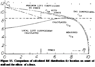
An example of the load distribution for a swept wing is given on figure 15. Based on simple sweep theory the corresponding section stall is also shown. Based on these two plots the wing would be estimated to first stall at the semi span station El – .68. The boundary layer flow increases the CLX as shown so that the actual first stall is located at M = .79.
The calculated lift coefficient where section stall is first encountered on a swept wing is lower than measured by approximately.01 as indicated in (9,a) or about 20%. The trend with changes in sweep angle and aspect ratio appears to be good so that the effects of changes can be expected to be determined with reasonable accuracy.
(8) Dynamic Stall:
a) Conner, Effect of Angle of Attack Rate on Max. Lift, NASA CR 321.
b) Rainey, Stall-Flutter Thin Wings, NACA TN 3622.
(9) Review Reports:
a) Harper, Stall Characteristics Swept Wings, NASA TN D2373.
b) Toll, Longitudinal Characteristics of Wings, NACA RM L5 3121b.
![]()
![]()
![]() Although the method given above is a good approximation for finding the station where stall first occurs it does not give satisfactory results for estimating the spanwise load distribution at high angles. This is due to the large increase of lift coefficient, especially on the inboard sections as shown on figure 7. For wings with. Л. = 45° analysis of (10,b) indicates the load distributin’! at high angles can be approximated by the equation
Although the method given above is a good approximation for finding the station where stall first occurs it does not give satisfactory results for estimating the spanwise load distribution at high angles. This is due to the large increase of lift coefficient, especially on the inboard sections as shown on figure 7. For wings with. Л. = 45° analysis of (10,b) indicates the load distributin’! at high angles can be approximated by the equation
15 -(50-000’ 15 + (50 – QL)/T
= The airfoil normal force coefficient, or: = Wing angle of attack. ft – Semi span distance from mid span = .5, ft’ is minus inboard of ft = .5 and plus outboard.
With the equation 8 and the distribution function shown on figure 16 an approximation of the load distribution on the wing operating at high angles of attack can be found for a known value of C* The distribution function of
(10) Spanwise Load and Section Lift Swept Wings:
a) Hunton, Section Characteristics of Two 45 Swept Wings, A = 6, NACA TN 3008.
b) Axelson and Haacker, A 45 Swept Wing with Body Combinations, NASA Memo 1-18-59A.
c) Graham, Low-speed Tests 45 Swept Wing, A = 3, R to 4.8 x 10 , NACA RML51H13, also TR 1208.
d) Hunton and James, Use of Two Dimensional Data in Predicting Loading with Flaps, etc., NACA TN 3040.
e) Woodward, Swept Back Wing With Constant Cu A= 35 , RAETR 71050.
figure 16 was set up for-A – = 45° and strictly applies only for wings with this angle; however, it is believed that it will be suitable for wings with sweep angles of 35 to 50 degrees.


