Composite Wings and Aeroelastic Tailoring
In this chapter, we considered divergence and aileron reversal of simple wind-tunnel models; torsional divergence, load redistribution, and aileron reversal in flexible- beam representations of lifting surfaces; roll effectiveness of an airplane with wings modeled as beams; the effects of sweep on coupled bending-torsion divergence; and the role of aeroelastic tailoring. It is clear that aircraft design is strongly influenced by aeroelastic considerations. In all of the cases explored in this chapter, the inertial loads are inconsequential and therefore were neglected. In Chapter 5, inertial loads are introduced into the aeroelastic analysis of flight vehicles, and the flutter problem is explored.
 |
Problems
1.
 |
Consider a rigid, wind-tunnel model of a uniform wing, which is pivoted in pitch about the mid-chord and elastically restrained in pitch by a linear spring with spring constant of 225 lb/in mounted at the trailing edge. The model has a symmetric airfoil, a span of 3 feet, and a chord of 6 inches. The total lift-curve
slope is 6 per rad. The aerodynamic center is located at the quarter-chord, and the mass centroid is at the mid-chord.
(a) Calculate the divergence dynamic pressure at sea level.
(b) Calculate the divergence airspeed at sea level.
Answers: qD = 150 lb/ft2; UD = 355 ft/sec
2. For the model in Problem 1, for a dynamic pressure of 30 lb/ft2, compute the percentage change in lift caused by the aeroelastic effect.
Answer: 25%
3. For the model of Problem 1, propose design changes in the support system that would double the divergence dynamic pressure by
(a) changing the stiffness of the restraining spring
(b) relocating the pivot point
Answers: (a) к = 450 lb/in; (b) xO = 2.513 in
4. For the model of Problem 1 as altered by the design changes of Problem 3, calculate the percentage change in lift caused by the aeroelastic effect for a dynamic pressure of 30 lb/ft2, a weight of 3 lb, ar = 0.5°, and for
(a) the design change of Problem 3a
(b) the design change of Problem 3b Answers: 11.11%; 17.91%
5. Consider a strut-mounted wing similar to the one discussed in Section 4.1.3, except that the two springs may have different stiffnesses. Denoting the leading – edge spring constant by к1 and the trailing-edge spring constant by к2, and assuming that the aerodynamic center is at the quarter-chord, show that divergence can be eliminated if кі/ к2 > 3.
6. Using Excel or a similar tool, plot a family of curves that depict the relationship of the aileron-elastic efficiency, n, versus normalized dynamic pressure, q = q/qD, for various values of R = qR/qD and 0 < q < 1. Make two plots on the following scales to reduce confusion:
(a) Plot R < 1 using axes —3 < n < 3
(b) Plot R > 1 using axes —3 < n < 3
Hint: Do not compute values for the cases in which 1 < R < 1.1; Excel does not handle these well and you may get confused. For some cases, you may want to plot symbols only and nicely sketch the lines that form the curves.
Answer the following questions: Where does aileron reversal occur? If you had to design a wing, what R would you try to match (or approach) and why? What happens when qR = qD? How does the efficiency change as q approaches qR? Why do you think this happens? What other pertinent features can you extract from these plots? Explain how you came to these conclusions.
7. Consider a torsionally elastic (GJ = 8,000 lb in2) wind-tunnel model of a uniform wing, the ends of which are rigidly fastened to the wind-tunnel walls. The model has a symmetric airfoil, a span of 3 feet, and a chord of 6 inches.
The sectional lift-curve slope is 6 per rad. The aerodynamic center is located at the quarter-chord, and both the mass centroid and the elastic axis are at the mid-chord.
(a) Calculate the divergence dynamic pressure at sea level.
(b) Calculate the divergence airspeed at sea level.
Answers: (a) qD = 162.46 lb/ft2; (b) UD = 369.65 ft/sec
8. For the model in Problem 7, propose design changes in the model that would double the divergence dynamic pressure by
(a) changing the torsional stiffness of the wing
(b) relocating the elastic axis Answers: GJ = 16,000 lb in2; xea = 2.25 in
9. For the model of Problem 7, for a dynamic pressure of 30 lb/ft2, compute the percentage increase in the sectional lift at mid-span caused by the aeroelastic effect.
Answer: 28.09%
10. For the model in Problem 7, for a dynamic pressure of 30 lb/ft2, compute the percentage increase in the total lift caused by the aeroelastic effect.
Answer: 18.58%
11.
Consider a swept clamped-free wing, as described in Section 4.2.6. The governing partial differential equations are given in Eqs. (4.94) and the boundary conditions in Eqs. (4.95). An approximate solution is sought for a wing with a symmetric airfoil, using a truncated set of assumed modes and the generalized equations of equilibrium: a specialized version of the generalized equations of motion for which all time-dependent terms are zero. Note that what is being asked for here is equivalent to the application of the Ritz method to the principle of virtual work (see Section 3.5). With the wing weight ignored, only structural and aerodynamic terms are involved. The structural terms of the generalized equations of equilibrium are based on the potential energy (here, the strain energy) given by
and the bending and torsion deformation is represented in terms of a truncated series, such that
where Nw and No are the numbers of assumed modes used to represent bending and torsion, respectively; n and фі are the generalized coordinates associated with bending and torsion, respectively; and Уі and &і are the assumed mode
shapes for bending and torsion, respectively. Determine the potential energy in terms of the generalized coordinates using as assumed modes the uncoupled, clamped-free, free-vibration modes of torsion and bending. For torsion
![]() n (j- 2) у
n (j- 2) у
£
For bending, according to Eq. (3.258), is given as
= cosh(a y) – cos(^y) – ві [sinh^y) – sin^y)]
with ai and ві as given in Table 3.1.
12.
 |
Work Problem 11, but for assumed modes, instead of using the expressions given therein, use
recalling that these functions are not orthogonal.
13. Work Problem 11, but use the finite element method to represent both bending and torsion.
14. Referring to Problem 11,12, or 13, starting with the virtual work of the aerodynamic forces as
__ r£ _
s w = (l’sw + me) dy
J0
where L and M are the sectional lift and pitching-moment expressions used to develop Eqs. (4.94), assuming a symmetric airfoil and using the given deformation modes, find the generalized forces Ei, і = 1, 2,…, N = Nw + Ne. As discussed in the text, generalized forces are the coefficients of the variations of the generalized coordinates in the virtual-work expression. (Hint: Neglecting the weight terms on the right-hand sides of Eqs. 4.92, we find L is the right-hand side of the second of those equations, whereas M is the negative of the right-hand side of the first and equal to eL.)
15. Referring to Problems 14 and 11,12, or 13, determine the generalized equations of equilibrium in the form
[*rn }=q {[ i + {S0i}
where q is the dimensionless dynamic pressure given by q/qD0; qD0 is the torsional divergence dynamic pressure of the unswept clamped-free wing, given by Eq. (4.55); {f} is the column matrix of all unknowns Пі = П /£, і = 1, 2,…, Nw, and фі, i = 1,2,…, Ne; and {H0} is an N x 1 column matrix containing the parts of the aerodynamic generalized forces that do not depend on any unknowns; and N = Nw + Ne. (Note that in application of the finite element, Nw = Ne refers to the number of finite elements, and N = 2Nw + Ne.) The N x N matrices [K]
and [A] are the stiffness and aerodynamic matrices, respectively. If Problem 11 is the basis for solution and elastic coupling is ignored, then the stiffness matrix [K] is diagonal because the normal modes used to represent the wing structural behavior are orthogonal with respect to the stiffness properties of the wing.
16. Referring to Problem 15, perform the following numerical studies:
a. Divergence: To determine the divergence dynamic pressure, write the homogeneous generalized equations of equilibrium in the form
1
=R} = [ K]-1[ A]R} q
which is obviously an eigenvalue problem with 1/q as the eigenvalue. After solving the eigenvalue problem, the largest 1/q provides the lowest dimensionless critical divergence dynamic pressure qD = qD/qD0 at the sweep angle under consideration. By numerical experimentation, determine Nw and Ne to obtain the divergence dynamic pressure to within plotting accuracy. Plot the divergence dynamic pressure versus sweep angle for a range of values for the sweep angle -45° < Л < 45° and values of the dimensionless parameters e/t (0.05 and 0.1), EI/GJ (1 and 5), and к = 0, ±0.5. Compare your results with those obtained in Eq. (4.129). Comment on the accuracy of the approximate solution in the text versus your Ritz or finite element solution. Which one should be more accurate? Discuss the trends of divergence dynamic pressure that you see regarding the sweep angle, stiffness ratio, and location of the aerodynamic center.
b. Response: For the response, you need to consider the inhomogeneous equations, which should be put into the form
[[K] – q[ A]] {£} = q {30}
Letting ar = 1°, obtain the response by solving the linear system of equations represented in this matrix equation. Plot the response of the wing tip (i. e., w and в at y = t) for varying dynamic pressures up to q = 0.95qD for the above values of e/t, EI/GJ, and к with Л = -25° and 0°. Plot the lift, twist, and bending-moment distributions for the case with the largest tip-twist angle. Comment on this result and on the trends of static-aeroelastic response that you see regarding the sweep angle, stiffness ratio, location of the aerodynamic center, and elastic coupling.
17. Consider the divergence of an unswept composite wing with к = 0, GJ/EI = 0.2, and e/t = 0.025. Using Eq. (4.126), determine the value of к, as defined by Eq. (4.125), needed to keep the divergence dynamic pressure unchanged for forward-swept wings with various values of Л < 0. Plot these values of к versus Л.
18. Using the approximate formula found in Eq. (4.126), derive a formula for qDact3/EI analogous to Eq. (4.113) and use it to determine the divergence dynamic pressure for swept composite wings when e < 0. Discuss the situations in which we might encounter a negative value of e. Which sign of к would you
expect to be stabilizing in this case? Plot this normalized divergence dynamic pressure for a swept composite wing with GJ/EI = 0.2 and ell = -0.025 versus Л for к = 0 and ±0.4.
19.
Consider the divergence of a swept composite wing. Show that the governing equation and boundary conditions found in Eqs. (4.120) and (4.121) can be written as a second-order, integro-differential equation of the form
with boundary conditions в(0) = в'(1) = 0 and with r = в/т. Determine the two simplest polynomial comparison functions for this reduced-order equation and boundary conditions. Use Galerkin’s method to obtain one – and two-term approximations to the divergence dynamic pressure td versus r. Plot your approximate solutions for the case in which GJ/EI = 0.2, e/l = 0.02, and к = -0.4, depicted in Fig. 4.28, and compare these with the approximate solution given in the text. For the two-term approximation, determine the limit point for positive e, noting that the exact values are r = 1.59768 and тD = 10.7090. Answer: The one-term approximation is
30
TD = 12 — 5r
The two-term approximation is
_ _________________ Ш0_________________
TD = 282 — 105r ± V3y15r(197r — 1,036) + ЦЇШ
The approximate limit point in the first quadrant is at r = 1.61804 and td = 11.2394. Within plotting accuracy, the two-term approximation is virtually indistinguishable from the exact solution when —10 < td < 10.
21. Consider a rigid body that represents the fuselage of a symmetric aircraft, to which are attached uniform, torsionally flexible wings that have the same properties as those in Problem 20. Assuming the aircraft is flying at constant speed with a constant roll rate, develop solutions for the same sets of parameters as asked for in Problem 20.

Aeroelastic tailoring is the design of wings using the directional properties of composite materials to optimize aeroelastic performance. The concept of aeroelastic tailoring is relatively new and came into the forefront during the design of forward – swept wings in the 1980s. Equation (4.112) shows that qD drops dramatically for forward-swept, untailored wings. The low divergence speed was a major hurdle in the design of wings with forward sweep. As discussed in this section, use of composite materials can help remove the disadvantages of forward sweep. Currently, aero – elastic tailoring is an integral part of the design of composite wings and can be used to improve performance in a variety of ways.
Composite materials are anisotropic, which implies different material characteristics (e. g., stiffness) in different directions. A simple beam model is helpful in developing an understanding of the behavior of composite wings. Such models may exhibit bending-torsion elastic coupling. Analysis of beams with elastic coupling is more involved, but it leads to helpful results.
Let us introduce such coupling in our beam equations. For anisotropic beams with bending-torsion coupling, the “constitutive law” (i. e., the relationship between
cross-sectional stress resultants and the generalized strains) changes from
where K is the bending-torsion coupling stiffness (with the same dimensions as EI and GJ) and ()" indicates the derivative with respect to y. A positive value of K means that a positive bending deflection will be accompanied by a nose-up twist of the wing, which is normally destabilizing for cases with the elastic axis behind the aerodynamic center.
Using the coupled constitutive law, the equations of equilibrium become
(GJв – Kw") = – qecaa – qc2cmac + Nmgd V,, (4.116)
^EIw" – Ke ^ = qcaa – Nmg
Consider again a wing that is clamped at the root and free at the tip, so that the boundary conditions that must be imposed on the solution are
 (4.117)
For composite beams, the offsets d and e may be defined in a manner similar to the way they were defined for isotropic beams: d is the distance from the y axis to the cross-sectional mass centroid, positive when the mass centroid is toward the leading edge from the y axis; and e is the distance from the y axis to the aerodynamic center, positive when the aerodynamic center is toward the leading edge from the y axis. Recall that for composite beams, the y axis must have different properties from those it has for isotropic beams, and the term “elastic axis” has a different meaning. For a spanwise uniform isotropic beam, the elastic axis is along the y axis and is the locus of cross-sectional shear centers; transverse forces acting through this axis do not twist the beam. For spanwise uniform composite beams with bending-twist coupling, no axis can be defined as the locus of a cross-sectional property through which transverse shear forces can act without twisting the beam. For such beams, we must place the y axis along the locus of shear centers, a point in the cross section at which transverse shear forces are structurally decoupled from the twisting moment. Although transverse shear forces acting at the y axis do not directly induce twist, the bending moment induced by the shear force still induces twist when K = 0.
 |
Differentiating the first equation with respect to y and transforming the set of equations so that they are uncoupled in the highest derivative terms вand w"", we obtain
 |
|
Multiplying the first equation by cos(A) and the second equation by sin(A) and subtracting the second equation from the first, we obtain a single equation in terms of в = в cos(A) – w’ sin(A) as
where ()’ now denotes d( )/dn as in the parallel development for the elastically uncoupled wing discribed previously.
 |
|||
The boundary conditions can be derived from Eqs. (4.117) as
The aeroelastic divergence problem with structural coupling has the same mathematical form as the problem without coupling, an approximate solution of which is given in the previous section. We can see that the parameters т and в can be redefined as
and, again, the divergence boundary can be expressed approximately in terms of the line
![]() 2
2
![]() т» = T +16eD
т» = T +16eD
Using the expressions for the parameters in the equation of the divergence boundary, we have
(4.124)
We can simplify this by introducing the dimensionless parameter

so that
As before, when the denominator of the expression for divergence dynamic pressure vanishes, it corresponds to infinite divergence dynamic pressure; crossing this “boundary” means crossing from a regime in which divergence occurs to one in which it does not. Setting the denominator to zero and solving for the tangent of the sweep angle, we obtain
where Лто is the sweep angle at which the divergence dynamic pressure goes to infinity. With this definition, we can rewrite Eq. (4.127) as
(4.129)
Again, divergence is possible only if -90° < Л < Лто. Thus, because of the presence of к as an additional design parameter, designers can at least partially compensate for the destabilizing effect of forward sweep by appropriately choosing к < 0, which for an increment of upward bending of the wing provides an increment of nose-down twisting. There is a limit to how much coupling can be achieved, however, because typically |k| < 0.86.
|
Чр 4d0
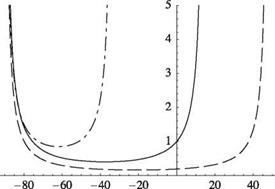
Figure 4.28. Normalized divergence dynamic pressure for an elastically coupled, swept wing with GJ/EI = 0.2 and e/t = 0.02; к = —0.4 (dots and dashes), к = 0 (solid lines), к = 0.4 (dashed lines) |
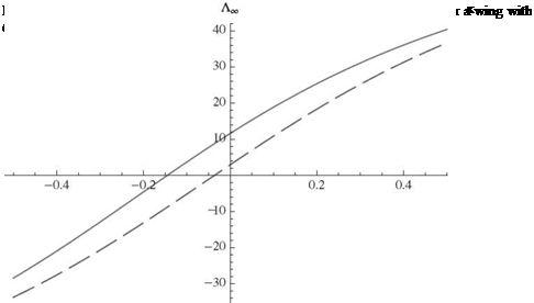
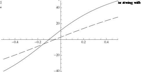
There are two main differences between the designs of isotropic and composite wings. First, it is possible to achieve a much wider range of values for GJ/EI. Second—and significantly more powerful—is the fact that composite wings can be designed with nonzero values of к. From Eq. (4.128), the value of Лто is decreased as к is decreased, which means that the range of Л over which divergence occurs is decreased. To confirm this and the previous statement about positive к being destabilizing, Fig. 4.28 shows results for к = -0.4, 0, and 0.4. It is clear that a composite wing can be swept forward and still avoid divergence with a proper choice (i. e., a sufficiently large and negative value) of к. Because forward sweep has advantages for the design of highly maneuverable aircraft, this is a result of practical importance. The sweep angles at which divergence becomes impossible, Лто, are also somewhat sensitive to GJ/EI and e/t, as shown in Figs. 4.29 and 4.30. Evidently, divergence-free, forward-swept wings may be designed with larger sweep angles by decreasing torsional stiffness relative to bending stiffness and by decreasing e/t.


