COMPRESSIBILITY EFFECTS
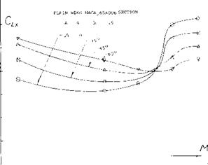
As the operating Mach number increases and exceeds the critical, the influence of compressibility becomes of major importance in the design and operation of swept wings. In addition to having a large influence on the drag, the effects of compressibility effect the usable operating CL prior to buffet, maximum lift, the longitudinal pitching moment and stability. The variation of the maximum lift coefficient with Mach number on figure 25 illustrates compressibility effects for a range of sweep angles of plain wings with an aspect ratio of 4. The effects of compressibility are also influenced by the nose radius, taper ratio, aspect ratio and load distribution. These parameters influence the location of shock waves and the corresponding areas of separation as a function of operating Mach number (14,e).
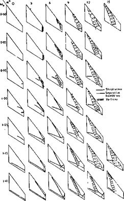
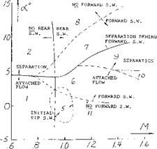
Flow at high Mach number. To illustrate the flow associated with swept wings at high Mach numbers as a function of the operating condition, the variation of the location of the vortices and the various shock waves formed on the wing are shown on figure 26. In the Mach number range below.85 it will be noted that with increasing angle of attack vortices are formed on the lead edge of the wing and tend to move inboard, leaving the tip stalled with separated flow at the high angles. At a Mach number of.95 a standing shock wave is first formed near the tip of the wing due to the local velocity exceeding M = ]. At this Mach number, the standing shock moves inboard with increasing angle of attack and again the leading edge vortex is formed. It behaves in the same manner as the vortex at the lower Mach numbers. At even higher Mach numbers in the neighborhood of 1.4, the standing shock wave is first formed near the trailing edge of the wing at zero angle of attack. With increasing angles a shock is formed toward the lead edge of the wing. The lead edge vortex is formed aft this shock. With further increases in angle of attack the tip of the wing becomes highly ineffective, especially at the higher Mach numbers. The highly complex flow pattern discussed above from (14,a) is typical and influences the conditions where buffet takes place. The various regions of flow for a 53.5° swept wing of A = 2.8 and Л = .333 are given on figure 27.
BUFFETING. As a result of the shock waves and vortex flow separation, buffeting is encountered on swept wings in the transonic flow region. This unsteady flow limits the operating CL to a so-called buffet limit. The limiting CL is influenced by the aerodynamic parameters of the wing, sweep angle, section type, taper ratio, aspect ratio and load distribution. Light buffet generally coincides with the drag divergent Mach number where the first shock wave is formed. The critical pitch up lift coefficient is generally at CL’s higher than those for the buffet boundary. This means that the pilot may be warned by structural vibrations prior to pitch up. As noted in (14,b) there are four different regions of the wing that must be considered for buffet effects:
1) The upper leading edge
2) The tip region
3) Downstream area influenced by leading edge vorticity
4) The trailing edge location.
These regions are identified on figure 27 as a function of angle of attack and Mach number. As a result of the combined effects in the above region of vortex formation and bursting along with the intersection of shock waves the CL for buffet, CL B, can be severely reduced, especially with wings where Л>50°.
|
О_________ і_______ і________ і_______ і________ і________ і_______ і_______ і_______ і——– 1——- 1——- 1— 0 .2 F.6 S /-0 /-2 Figure 25. Maximum lift characteristics of plain aspect ratio for swept wings as influenced by compressibility (14,e). |
The results of tests conducted to M = .93 indicated that for wings in the sweep range of 25 to 45° and aspect ratio 4 to 6 the highest buffet lift coefficient is obtained with the wing with the best aerodynamic efficiency This is illustrated in figure 28.
When operating at transonic Mach numbers with swept wings of high aspect ratio the separation and associated buffet can be delayed to a higher speed with the addition of bodies on the upper surface of the wing (14,f). These bodies cause an actual reduction of drag as well as an improvement of the pitching moment characteristics of the configuration, figure 29. The bodies reduce the separation by eliminating the extensive cross flow in a manner similar to fences. Such bodies have been used on commercial transport aircraft with a reported improvement in cniising speed.
|
Figure 26. Variation of lead edge vortex separation shock waves and separated boundaries as a function of Mach number. Aspect Ratio = 2.8, Sweep Angle = 53.5 . |
NUMBERS INDICATE REGIONS OF:
(1) ATTACHED FLOW, NO SHOCK WAVES.
(2) SEPARATION AT THE LEADING EDGE FORMING A VORTEX.
(3) FORWARD SHOCK WAVE ONLY, NO SEPARATION.
(4) FORWARD SHOCK WAVE ONLY, SEPARATION AT THE SHOCK FORMING A VORTEX.
(5) INITIAL TIP SHOCK WAVE, WITH OR WITHOUT A REAR SHOCK.
(6) FORWARD AND REAR SHOCK WAVES PRESENT, NO SEPARATION.
(7) FORWARD AND REAR SHOCK WAVES PRESENT, SEPARATION BEHIND THE FORWARD SHOCK FORMING A VORTEX.
(8) REAR SHOCK WAVE ONLY, LEADING-EDGE SEPARATION FORMING A VORTEX.
(9) FORWARD AND REAR SHOCK WAVES INTERSECTING ON THE WING WITH A STRONG OUTBOARD SHOCK WAVE CAUSING SEPARATION.
(10) FORWARD AND REAR SHOCK WAVES INTERSECTING AT THE TRAILING EDGE.
(11) REAR SHOCK WAVE ONLY, NO SEPARATION.
|
Figure 27. Regions in which shock and/or separation occur on a complete wing. Aspect Ratio = 2.8, Sweep Angle = 53.5 . |


