EQUATIONS OF MOTION OF THE CONTROL SYSTEMS
Up to this point in our development of the subject we have not found it necessary to consider the dynamics of the vehicle’s control systems per se, although the omission of this feature was pointedly noted in the previous section. In fact the dynamics of control systems not only enter into closed-loop behavior but are also implicit in the stability of vehicles with free controls. When the controls are reversible (i. e. when an external force applied at the surface can cause it to move), the stability with free controls may be appreciably different from that with fixed controls. This case can be thought of in a sense as belonging to the feedback class of control problems, since the control angles are then governed by certain inherent aerodynamic and inertial feedbacks.
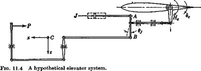
The wide variety of control system types and configurations in common use, and the variability of the schemes used to provide power or force amplification make it virtually impossible to present a universal analysis of any use. We therefore select one hypothetical model of a control system, and show how its equations of motion are derived. Generally speaking, a similar procedure would apply to other cases. The model is that depicted in Fig. 11.4. It consists of a rigid elevator surface, connected by a rigid frictionless linkage to the pilot’s control and to a hydraulic jack. The airframe structure to which the system is attached is also assumed to be rigid. The external forces acting are the pilot control force P, the jack force J, and the aerodynamic hinge moment He. Gravity is neglected since it is essentially
|
|
a constant that only affects the equilibrium position slightly. The system has two degrees of freedom relative to the frame FB, i. e. de and Oj. The control system shown represents a power assisted elevator, and does not incorporate explicitly any provision for closed-loop positioning of the elevator. This would require a somewhat different physical arrangement, and its governing equation would be different from that derived below.
We obtain the equations of motion by applying Lagrange’s equation
(5.12,3) , the procedure being somewhat analogous to that used in Sec. 5.12. In this application, since rigidity has been assumed, the strain energy V is zero. en stands for either de or 6j, so that there are two equations of motion. As in Sec. 5.12 the generalized force n must include the inertia forces associated with acceleration and rotation of the reference frame FB.


