HIGH LIFT DEVICES FOR SWEPT WINGS
 |
 |
 |
The use of swept wings on transport aircraft has led to the development and application of highly sophisticated devices to increase the lift and reduce the adverse pitching moment at the takeoff and landing conditions. With the first generation of swept wing jet airplanes the devices to increase lift were relatively simple. The need to increase the payload while maintaining the same airport restrictions resulted in the use of more advanced high lift devices. The STOL transport with field length requirements of 3,000 feet or less force the use of even more advanced devices for increasing lift of swept wing aircraft.
|
|
WING LOADING. The need for high lift devices on swept wing is apparent when the wing loading is examined. Fighter airplanes typical of World War II could be pulled out of a dive (at well below the speed of sound) with 10 “g’s” (if needed) without stalling. Their wing loading was in the order of 40 lb/ft2(below 200 kg/m2). By comparison, a modern transport airplane may have wing loadings of 100 lb/ftг (more than 400 kg/n/). For the same landing speed, the airliner should thus have a maximum lift coefficient, 100/40 = 2.5, or at least two times as high as that of the assumed fighter. This means tha: CLX should be in the neighborhood of 2.7 to 3. When operating at these high lifts the induced drag coefficient may then be four times as high, and the total D/L at CLX possibly three times as high. This means roughly a sinking speed also three times as high as that during the landing approach of the fighter some 20 years earlier.
DESIGN FOR HIGH CLX. Due to the high wing loading the design of auxiliary devices for high lift on swept wing requires consideration of the drag and pitching moments characteristics as well as the overall complication of the mechanism. Because the flap and slat systems become more complex as the requirement for CLX is increased it becomes a major design problem to develop the simplest and most effective total system. This is apparent when one observes the wing during the takeoff and landing conditions when it appears to come apart in all directions as a result of deploying the various high lift flaps and slats. The choice and location of the high lift devices is dependent on the geometry of the wing which is determined based on the high speed cruising requirements.
 To determine the best configuration of the multi-element airfoils, the lift requirements are established spanwise on the wing so that at each station two dimensional data can be applied. The data on the high lift characteristics of leading and trailing edge devices are given in Chapters V and VI. The combination of slats, leading and trailing edge flaps for a swept wing should be selected so that the stall first occurs inboard to provide a stable moment curve, a negative – pitching moment, through the stall. The high lift devices should also be selected so that the drag is compatible with the engine thrust during take off and emergency landing conditions.
(16) Leading Edge Flaps:
a) Griner, Lateral and Longitudinal Stability A = 47.7 , A = 6, NACA RM L53G09.
(17) Trailing Edge Flaps:
a) Naeseth, Double Slotted Flaps – Swept Wing Transport, NASA TN D103.
b) Capone, Longitudinal Characteristics Subsonic Transport, NASA TN D5971.
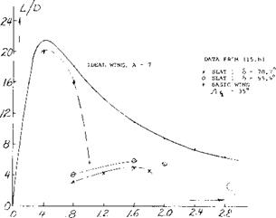
In addition to developing a wing with high lift and good pitching moment characteristics it is necessary to maintain minimum drag so that peak take off and landing performance can be obtained. This is necessary as the drag must be compatible with the engine thrust, especially during emergency conditions. To determine the best performance that can be obtained the lift drag ratio of the wing is found based on the drag coefficient from the equation
CD =CD0 +CL2/efTA (9)
Where e is the span efficiency and C Do is the drag coefficient at zero lift. Thus, for any wing the ideal or best lift drag ratio can be established as a function of CL. The actual performance can then be compared to the ideal to determine where improvements are needed.
On figure 30 the ideal lift drag ratio for A = 7 compared with test data (17,a) of various combinations of flaps and leading edge devices. From such a study the best combinations of high lift devices can be found for the wing at any lift coefficient.
Because of the boundary layer transport as influencing maximum lift, especially inboard, high lift devices must be very effective, especially with those used outboard. For instance as was shown on figure 7, the sectional lift coefficient is twice as high as the corrected two dimensional at the.383 station for a swept wing with A = 45° and A = 6, while at the tip maximum lift coefficients are nearly equal. Thus, to obtain the required characteristics of C L and Cn large increases in CLX are needed for the outboard sections if the entire wing is stalled a: the same angle.
In (9,a) it was shown that leading edge devices covering as much as the outer 75% of a 35° swept wing would provide sufficient protection from stall to obtain a stable pitching moment. With – Л = 45° only one combination tested gave the required stable pitching moment while at A = 60 the moment remained unstable.
|
|
|
Figure 30. Maximum lift drag ratio for wings of a fixed aspect ratio in comparison with actual wings with high lift devices. |
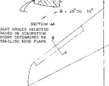
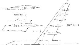
LEADING EDGE SLAT. The slat, figure 1, Chapter V, is used on many swept wing airplanes to prevent stall on the leading edge. Generally, the slats cover approximately 50% of the span and are installed in segments so their angle can be varied to get the desired stall protection. The slats increase CLX of the airfoil with or without trailing edge flaps. The design and performance improvement of the slat as used on two dimensional sections is covered in Chapter VI. In the application of slats to a swept back wing to prevent the unstable pitch up moment while obtaining maximum lift, it is necessary to use as large a surface as possible (15,c). The tip chord of the slat should be as large as practical with 30% of the wing chord being considered a maximum. The slat should extend inboard as far as possible without causing the unfavorable pitch up moment as stall approaches. The slat should also be extended as far outboard as possible. However, it is not necessary to extend it outboard of the point shown on figure 31. The ends of the slats are generally cut off on a plane normal to the quarter chord point, also shown on
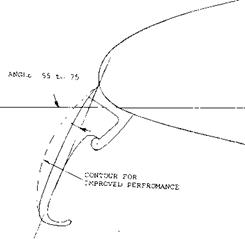
figure 31. Further details on the design of slats are given in Chapter VI, including load and moment data. In the selection of the slat maximum operating angle it is necessary to use a deflection that will cover the stagnation point. This requires a much larger angle than is normally covered in the literature, especially for wings with very high values of CLX.
|
10-20°/eU-
Figure 31. Slat geometry as installed on a swept wing to protect tip stall (15,c). |
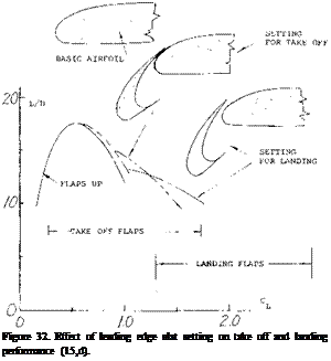 The choice of the slat position is a function of the position of the trailing edge flaps and is determined by the lift drag ratio of the system (15,d). Shown on figure 32 is the lift drag ratio as a function of operating CL for the slats retracted at take off position and at landing for a typical transport airplane. The triple slotted trailing edge flaps are at the best angle for peak performance. It should be noted that with the flap set for the take off the slat is operating at approximately 45° with no slot, or in the sealed position. This is done to achieve peak performance, maximum L/D and ^LX •
|
||
|
||
|
 |
|
|
||
|
||
|
||

![]()
|
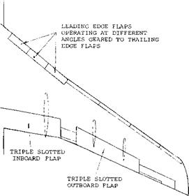
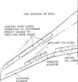
Figure 35. Typical transport aircraft wing configuration including slat and flap locations.
As shown on figure 35, the wing incorporates triple slotted flaps located inboard and outboard. Between the flaps an inboard aileron for lateral control, and on the outboard section another aileron is used. The triple slotted flaps operate at angles varying from 5° to 40° depending on the flight mode. The highest flap angle is useful just before touchdown. Also employed on the wings are flight and ground spoilers. The flight spoilers are used to increase the drag during descent to limit air speed and are located just about the outboard flaps. The ground spoilers, located above the inboard trailing edge flap, are used to kill the lift on touchdown to provide improved braking forces.
The wing described is typical for that found on aircraft introduced in the 1960’s. Later transport aircraft use even more complicated devices, as the maximum aft during both take off and landing is extremely important with regard to the economics of swept wing aircraft. For instance, the Kruger flap is curved during its deployment as shown on figure 33. With the introduction of STOL aircraft the devices will become even more complicated find extensive and will incorporate all the concepts discussed in Chapters V and VI.


