Interfering wings and ground effects
5.7 On classical and swept types of aircraft, various lifting surfaces may be placed in the flowfield of others and may thus interfere with one another. In most cases, the vortex wakes behind wings play an important part. We want to give a brief survey here of the main physical interference effects that must be borne in mind and understood in aircraft design, under the following main headings:
the structure of vortex wakes;
a small wing downstream of a large wing, e. g. the tailplane in the downwash field of the main wing;
a small wing upstream of a large wing, e. g. foreplanes; two similar wings close to one another, e. g. biplanes or tandem wings; a wing close to the ground, i. e. in the flowfield of its image in the ground; intersecting wings, e. g fins and tailplanes.
All these problems have some aspects in common, which could be exploited to develop a unified theoretical treatment. This will be discussed first.
In all cases, the flowfield of a thick lifting surface must be determined. If the velocity components induced by it at the location of the other lifting surface are known, then the properties of the latter can be calculated. If the interference is mutual, that is, if the properties of the wings involved must be expected to be strongly interdependent, then an iterative procedure can be
applied to obtain the final answer. Such a procedure should converge since we know, for physical reasons, that a solution exists and that it will usually be a relatively small perturbation of the solution for the lifting surface alone in an undisturbed stream. In any case, the interference should not change the type of flow over any part of a well-designed aircraft.
The means for carrying out such a procedure are already available for inviscid subcritical flows: С C L Sells (1969) has developed a practical method for computing the induced downwash field on and off the wing plane for wings with a given load distribution; and J A Ledger (1972) has developed a similar and compatible method for computing the velocity field of wings of given thickness. The framework of the RAE Standard Method can then be used to calculate loadings and pressure distributions in inviscid flow; an iterative design procedure, as developed for single wings by С C L Sells (1974), can in fact be carried out along the same lines as those described in Section 4.3. However, such a unified treatment has not yet been worked out. The older methods discussed below are, therefore, ready to be superseded, but they may be used, nevertheless, to explain the physical phenomena.
Whichever way the problem is treated, there remains one fundamental difficulty whenever free vortex wakes are involved: the structure and position of such a vortex sheet are, in general, not known beforehand and it is difficult to determine them, theoretically or experimentally, when they need to be known. Therefore, we begin with a brief discussion of vortex wakes in the context of interfering wings, bearing in mind the properties of vortex sheets and their rolled-up cores already described in Sections 2.4 and again in 6.3.
On a well-designed classical or swept aircraft, vortex sheets spring from separation lines which are firmly fixed along aerodynamically sharp edges. Uncontrolled separations lead to vortex formations, such as the body vortices discussed in Section 5.5 in connection with Figs. 5.32 to 5.36, which are generally undesirable and unpredictable. Therefore, we consider here only well – ordered flows with fixed separation lines, generally along the trailing edges.
|
RAE IOO t/c = 0-1 A = 6 c*=7° x/c = 4 Fig. 5.61 Total-head contours in a transverse plane behind a rectangular wing at low speeds. After Maskell (1972) |
The structure of the vortex sheet trailing behind the main wing has already been discussed several times, especially the rolling-up along its free edges (see Section 4.6). A typical shape of the wake behind a simple unswept wing can be seen in Fig. 5.61, as measured by E C Maskell (1972). Lines along which the total head differs from that in the mainstream by a certain amount indicate several features which are important in the present context: that the presence of a viscous wake does not conceal or efface the existence of a layer of vorticity which may be regarded as a thin sheet lying within the contours indicated; that this sheet is nearly flat over much of the span and rolls up
near the edges into vortex cores; and that the sheet is displaced downwards relative to the wing by a significant amount. These measurements were made at a distance behind the wing which roughly corresponds to that of a tailpla – ne on an aircraft, i. e. about one semispan behind the wing. It is understandable, therefore, that further upstream and especially when considering the wing itself, a flow model with a plane vortex sheet along the mainstream direction should be adequate, except in the tip regions, as explained in Section 4.6. Further downstream, on the other hand, the rolling-up process will continue and eventually most of the vorticity will be concentrated in the two cores. As stated before, rolled-up vortex sheets are extraordinarily stable anti-dissipation devices, and so the two vortex cores behind a wing may persist in tightly rolled-up form up to a distance between 10^ and 10* times the wing span, as can readily be observed in the sky.
This persistence and stability of vortex cores is of practical importance since an aircraft flying into the swirling vortex wake of another aircraft ahead of it may be thrown out of control, especially if the leading aircraft is bigger. This risk is so serious that separation distances between large aircraft of about 10 km are imposed for reasons of safety. This in turn implies long separation times, especially in airport operations and, in view of the severe economic and operational consequences, much work is being done to find out more about the structure of vortex cores and also to try to find means for dissipating them at shorter distances. Some of this work has already been mentioned in Section 4.6, and we refer here also to further work on the structure and on the decay of trailing vortices by J N Nielsen & R G Schwind (1970), G M Williams (1972), D W Moore (1972), N A Chigier & V R Corsiglia (1972),
V R Corsiglia (1973), P G Saffman (1973), I Tombach (1973), V J Rossow (1973),
P F Jordan (1973), and Z El-Ramly et al. (1975). A simple and effective method for estimating the rolling-up and the velocity distributions has been developed by A J Bilanin & C duP Donaldson (1975). There are also some review papers on the behaviour of vortex cores by P L Bisgood et al. (1970), R L Maltby & F W Dee (1971), G H Lee (1973) and (1975), C duP Donaldson & A J Bilanin
(1975) , as well as the proceedings of a conference on aircraft wakes (see J H Olsen et al. (1971)). P L Bisgood (1973) has reported especially on measurements made in flight.
Several mechanisms have been identified which may disrupt the cores: vortex breakdown (see e. g. M G Hall (1972); also Section 6.3); instabilities which occur in vortex pairs, such as lateral waves and the formation of loops’, or the generation of lateral disturbances, such as pairs of counterrotating cores along the main cores (see e. g. J К Harvey (1971), H Bippes (1973), J P Narain & M S Uberoi (1973)). The formation of loops is probably the most powerful effect of these in bringing the vortex trail to an end. It was first observed in flight tests by R Rose & F W Dee (1963). The mutual interaction between the pair of trailing vortices begins a long way behind the generating aircraft with a sinusoidal distortion in the horizontal plane. Its amplitude increases with time until, eventually, the two trails appear to touch and join up to form elongated loops. These persist for a considerable time. Finally, the loops disperse and the trail disappears. E C Maskell (unpublished; see P L Bisgood et al. (1970)) has derived semi-empirical relations for the interaction time from a dimensional analysis of a simplified model of the flow, which describes the observations well. S Crow (1969) and (1970) has treated the cause of looping as an instability of the two cores (see also A Mager (1972)).
Attempts have been made to reduce the strength of the vortex cores or to provoke an earlier breakdown by special shaping of the wing tips.
This has been proposed by several people (see e. g. V J Rossow (1975)), and we refer here to the Sikorsky tip shape where the trailing edge is curved so. that the wing chord decreases rapidly to a small value at the tip (see J Rorke & R Moffitt (1973)). This may be effective on helicopter blades where a similar problem arises: to reduce the interference between the trailing vortex from one blade and the following blade. On the whole, none of these problems can be said to have been clarified satisfactorily.
The problem of the far wake matters especially when the aircraft approaches the ground. It can readily be seen that the vortex sheet with its rolled-up cores as in Fig. 5.61 cannot continue to descend without modification (see e. g. P L Bisgood et at. (1970) J N Hallcock (1972), С E Brown (1975)). When the cores get near the ground, their rate of descent is checked when the effect of the image vortices in the ground is felt. Flight experiments by F W Dee & 0 P Nicholas (1968) have shown that the motion of the cores agrees moderately well with the paths predicted by a simple theory for a pair of concentrated vortices above an infinite plane, that is, the cores follow curves, when projected on to the crossflow plane, of the form 1/y^ + 1/z^ = constant. But a closer experimental inspection of the flowfield induced by trailing vortices near the ground by J К Harvey & F J Perry (1971) has revealed that the crossflow over the ground leads to suction peaks underneath each core, followed by "secondary" flow separations from the ground. These separation surfaces are also vortex sheets which roll up into cores, with vorticity in the opposite sense to that in the "primary" cores behind the aircraft. It appears that the secondary cores grow to a strength comparable with that in the primary cores and induce these to rise again quite rapidly away from the ground, whereas the secondary cores are evidently prevented from spiralling around the free primary cores by their feeding vortex sheets which tie them to the ground.
As a very rough picture, we may visualise that the vortex cores from the aircraft stabilise at a height of about one half of the wing span above the ground. At the same time, the two cores begin to move apart. At the stabilised height, each core is moving laterally away from the aircraft with a speed about equal to the rate of descent of the aircraft, i. e. at between 2 and 3 m/sec. This speed is of the same order as possible crosswinds on the airfield. Crosswinds greater than that may blow the wake sideways away from the runway and make the imposed separation distances unnecessary. But until the fundamental fluid mechanics of these vortex motions and the conditions in the atmosphere near the ground are clarified further, no steps to relax the regulations can be taken.
Consider now the relatively simple flow past the taiVptane of an aircraft. The flow direction there is inclined downward by an amount v/Vg = otp which, to a first order, may be taken to be the doumwash that is self-induced by the bound and trailing vortex system of the main wing: in general, the tailplane is too small and too far away to affect the loading and hence the vortex system of the main wing in return. This downwash usually detracts from the purpose of the tailplane, which is to make a stabilising contribution to the pitching moment of the aircraft:
Here, S^, and are the plan area and moment arm of the tailplane and A<Xq is the difference between the no-lift angles of wing and tailplane, related to the tail setting, which might be changed during flight for trimming purposes;
and ry is an efficiency factor which differs from unity when the flow near the tailplane is significantly non-uniform (this will be discussed further in Section 5.8 below). When considering the longitudinal stability of an aircraft, we have to know also the change of the pitching moment with the angle of incidence, which is proportional to
![]() (5.30)
(5.30)
 |
|
Thus we are interested in the value of otjj in relation to a and also of the slope dojj/doi. If we know aD in terms of cu ■ С^/тгА, then these quantities can be worked out for a given wing.
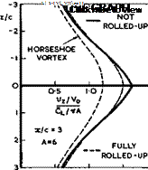
Fig. 5.62 Downwash behind rectangular wing
Fig. 5.62 shows some typical downwash distributions at and above and below the centreline one semispan behind a simple rectangular wing, as calculated by I FlUgge-Lotz & D KUchemann (1938). Several features should be noted: that there is a relatively small difference between the downwash values calculated for a fully-rolled-up vortex sheet and for one which is still flat and not rolled-up at all – experimental evidence so far has shown that the values for the not-rolled-кр vortex sheet are closer to reality, as would be expected from the results in Fig. 5.61; that the representation of the vortex wake by a single horseshoe vortex gives quite different values which are inadequate; that the downwash depends strongly on the vertical position of the tailplane relative to the vortex sheet. The latter implies that the downward motion of of the trailing vortex sheet must be taken into account when determining the position of the tailplane relative to the vortex sheet. A first approximation to the position of the vortex sheet can be obtained by integrating the values of vz(x) along x. A typical result of such an integration is shown in Fig. 5.63. The downward displacement of the vortex sheet is significant.
Downwash curves as in Fig. 5.62 also depend strongly on the actual spanwise loading over the main wing. For example, the peak of the downwash curve is much sharper than that shown in Fig. 5.62 for a wing with elliptic spanwise loading; it reaches values greater than 2Cl/ttA, i. e. it overshoots the value at infinity behind the wing as a result of the contribution from the bound vortices. The value of vz(x, y) is also sensitive to details of the actual spanwise loading, such as holes in the CL(y)-curve near the centre of sweptback wings. We can see from Fig. 4.22 how this may lead to the shedding of trailing vortices of the opposite sign which contribute an upwash component near the centreline. A similar effect, in reducing the downwash, may be achieved on any wing by even a small out-out in the wing planform which reduces the chord near the centreline or in the wing-fuselage junction.
For the same reason, the downwash at the tail is sensitive to other changes in the spanwise loading, such as those brought about by the deflection of part-span flaps. Quite often, the downwash may vary along the span of the tailplane so that the spanwise loading over the tailplane is affected.
With regard to flight stability and specifically in some manoeuvres, changes of the downwash with the angle of incidence matter (see (5.30)). The tail – plane may then move relative to the vortex wake of the main wing. If the tail is initially in a low position just below the sheet, then increase in the angle of incidence may move it away from the sheet, with a consequent reduction in downwash (see Fig. 5.62). This is beneficial and increases the effectiveness of the tail. Alternatively, a high-tail position may have the opposite effect. Clearly, a position where the tail is likely to move through the vortex sheet should be avoided. This is not always possible when the aircraft is flown close to the limits of normal flight conditions, especially at high angles of attack near or, inadvertently, beyond the stall when a high tail may move into a Wide wake of separated flow behind the main wing, where the total head (and hence rvp ) is very low. As explained by H H В M Thomas
(1971) , such critical flight conditions are generally only encountered in the course of a manoeuvre. Handling difficulties may then on occasion lead to a complete loss of control. Thomas has also pointed out design features which can help to avoid these dangerous situations and which should enable the pilot to handle the aircraft safely.
Consider now what happens if a small wing, or foreplane, is put upstream of a larger wing, which is then influenced by the vortex wake shed by the small wing. Again, we assume, to a first order, that the loading over the small wing is not influenced by the presence of the large wing. But the loading over the large rear wing may then be strongly affected by the wake of the small wing: the rear wing is not just subjected to a nearly uniform downwash
but, if its size is large enough, it will pick up the whole upwash and down – wash field in the "Trefftz plane" of the forward wing. In the extreme case, the rear wing will straighten out the flow completely and thus experience an additional lift force which is equal and opposite to that of the wing in front. Hence, the overall lift of the combination of the two wings is not changed.
But a pitching moment is generated and such a foreplane may, therefore, be regarded principally as a trimming device (see e. g. S В Gates (1939)). In reality, matters depend very much on the actual sizes of the wings and on their relative positions, and detailed calculations are needed to determine the actual forces and moments. Such calculations have been carried out for particular combinations of two wings in a supersonic flow by M С P Firmin &
W J Bartlett (1960) and compared with the results of experiments. They demonstrated that the flowfield of the foreplane induces overpressures and suction peaks on either side of the spanwise station of the (in this case fully – rolled-up) vortex core, and that these peaks are situated along Mach lines and are attenuated with distance downstream. They found that it is necessary to take account also of the induced crossflow in determining the pressure distribution. Similar calculations, allowing also for the presence of a body and making the assumption that the whole configuration may be regarded as aerodynamically slender, have been done by P R Owen & E C Maskell (1951). It turned out in all the cases considered that the actual amount of lift taken up by the rear wing and the actual pitching moment obtained is a matter of fine detail and hence rather uncertain. Detailed investigations for flows at subsonic speeds have not yet been carried out, but the general effects must be expected to be of a similar nature.
The greatest uncertainty and the weakness of the available methods for estimating the properties of such flows stem from the fact that the relative ‘position of the free vortex sheet and its structure are not known in advance. The degree of rolling-up and the distance of the vortex sheet from the affected wing obviously determine the results to a large extent. In addition, the actual shape of the sheet may be distorted by interference from neighbouring surfaces. During manoeuvres, the vortex cores may assume asymmetric positions with regard to the rear wing, and possibly to a fin, and thus induce also side forces as well as rolling and yawing moments. All these effects may be time-dependent and in their complexity very difficult to determine, either theoretically or experimentally. Foreplanes with free trailing vortex sheets can, therefore, not in general be regarded as suitable design elements for aircraft.
We may mention in this context an interesting phenomenon which has been observed by J D Bird (1952) in the wake of cruciform wings in the shape of an X set at an angle of incidence. The two pairs of fully-rolled-up cores far downstream interact in a manner similar to that of two vortex rings, as described by H von Helmholtz (1868). Whereas the lower pair draws apart, the upper pair moves towards one another and downwards; eventually, they pass through in between the lower pair and the whole process, which has been called leap-frogging, is repeated. Note that this motion differs from that of a vortex pair near the ground, described above; there, the rotation about the lower (image) pair is in the opposite sense to that of the pair above the ground; this keeps them apart.
Consider now the interference between two wings which are approximately of the same size and relatively close to one another, i. e. of the order of one wing chord apart horizontally or vertically. The interference is then mutual and the simplifying assumptions made above are no longer appropriate. Although such configurations as tandem wings (see e. g. В Laschka et al. (1969),
R Dat & Y Akamatsu (1971), J Becker (1974)) and biplanes (see e. g. D Kuchemann (1938)) are rarely found in practice nowadays, we mention here some physical features of such interfering flows, which are of general interest and may be useful in other applications.
In the biplane theory у an iterative procedure was applied, whereby the properties of the two wings in isolation were calculated first, using the classical aerofoil equation (4.56) or (4.81). These solutions were then used to determine the velocity components induced by one wing at the position of the other and subsequently the properties of each wing in these induced flows could be worked out. This procedure could be repeated. It was found to converge rapidly: sometimes, one step or, at the most three steps were sufficient in the case of biplanes. Unlike many modern computer procedures, where the
. 2 3
number of iterations may be of the order of 10 or 10 , such an iteration is based on known physical properties and hence can be expected to converge much more rapidly.
In the biplane theory again, some simplifications were successfully applied to take into account that one wing induces at the other a flow with an increased or reduced velocity V = Vq + Av, and that the flow is also curved with a radius of curvature in planes у = constant:
Within classical aerofoil theory, by (4.48) and (4.56), the velocity change may be interpreted as a change in the geometric angle of incidence:
and the curvature of the flow as another:
according to H Glauert (1926) and E Pistolesi (1936). The last relation implies that a plane aerofoil in a curved stream has the same lift as a suitably cambered aerofoil with the opposite curvature in a parallel stream. Both relations apply only in irrotational flows when the perturbations can be taken to be small and when non-uniformities in the field, i. e. changes of Дv and of r in the directions of either of the three coordinates, can be assumed to be insignificant. What happens when such non-uniformities matter and are associated with vorticity in the stream will’ be discussed in Section 5.8. For biplanes and similar configurations, the approximations (5.32) and (5.33) were shown to be adequate and allowed a theory to be developed entirely within the framework of classical aerofoil theory, described in Section 4.3. Biplanes also turned out to be one of the few cases where it is usually permissible to assume that one wing is in the farfield of the other so that, for the purpose of calculating the interference effects, the bound vortices can be replaced by a single "lifting line" (in the sense described in connection with Fig.3.3). But there are also exceptions (see D KUchemann (1938)), where the assumption of a lifting line leads to significant errors: this concept, however attractive it may seem, should always be handled with extreme caution.
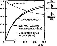
Biplanes also represent an instructive example of a non-planar wing system which may have a lower vortex drag than a single wing of the same span and overall lift. The lowest vortex drag can be determined from considerations of the flow in the Trefftz plane, as explained in Section 3.2. This problem was solved by M M Munk and L Prandtl and the solutions may be found in L Prandtl & A Betz (1927). The result may be expressed in terms of the vortex drag factor, defined by (3.38), and a typical example is shown in Fig. 5.64. The overall vortex drag of a biplane is always smaller than that of the monoplane which carries the same overall lift and which has the same span as the larger of the biplane wings, and the value of Ky may fall considerably below unity as the wings move further apart. Alternatively, a monoplane must have an aspect ratio which is 1/ -/Ky times that of the biplane to carry the same lift as the biplane for the same vortex drag. On the other hand, a biplane has usually a larger surface area and hence a greater skin-friction drag than the
corresponding monoplane. Also, it has been found that mechanical high-lift devices are less effective on biplanes than on monoplanes. Thus the aerodyna-
 LIVE GRAPH
Click here to view
Fig, 5.64 The vortex drag factors of biplanes and of a wing near the ground mic advantages of biplanes were largely offset and what remained was the possibility of designing a light structure for two wings joined by struts. Even this advantage was eroded and the biplane was considered doomed when structural engineers learnt how to design lightweight structures for cantilever monoplane wings (the first being H Junkers in 1915).
Finally, we mention an interesting interference effect between two wings in a supersonic stream: a non-tifting biplane can be designed to have no wavedrag due to volume, i. e. Kq » 0 in (3.44). As pointed out by A Busemann (1935), the two outer surfaces can lie along the mainstream and the two inner surfaces facing each other may be curved as compression and expansion surfaces in such a way that the two weak wave systems cancel each other completely so that the air emerges again from between the trailing edges as a parallel stream and no disturbances are left behind.
We turn now to the flow past a wing near the ground, which may be regarded as an interference between the wing and its image in the ground. (This problem is closely related to that of a wing within the constraints of the solid walls of a windtunnel. This will not be discussed here. See e. g. H C Garner et at,
(1966) ). The two wings are now of exactly the same size but, in contrast to biplanes, the circulation about one is equal and opposite to that about the other. This has remarkable consequences. Consider first the vortex drag when a wing approaches the ground. This problem has been treated in the classical way by P de Haller (1936) who calculated the minimum vortex drag for a wing of given span and lift. Earlier, C Wieselsberger (1921) had calculated the vortex drag on the assumption that the spanwise loadings were elliptic. Results from both calculations are shown in Fig.5.64. They do not differ much, but the ground effect has the opposite trend with distance h from the interference effect found for biplanes: it increases as the ground is approached. (Note that the definitions of h do not strictly correspond in the two cases: the ground effect would appear to be relatively even stronger if the same definition had been used). This reduction of the vortex drag implies a reduction of the induced angle of incidence and hence an increase of the effective angle of incidence at the wing, for a given geometric angle. It follows that the ground effect produces an increase in the overall lift slope of threedimensional wings, as the distance becomes smaller.
Such a powerful effect must be accompanied by strong repercussions on the other forces and moments and on the detailed pressure distribution over the wing, especially on swept wings where different parts will be at different distances from the ground. The effectiveness of high-lift devices, in particular, will be affected during take-off and during the landing flare. In view of this, it seems strange that not much work has yet been done to determine the properties of threedimensional swept wings. However, an extension of the RAE Standard Method, as described above, has now been provided by С C L Sells
(1976) , which allows an iterative calculation of the flow past a thick cambered wing near the ground, and which is accurate as well as practical. There is also a theory by В Laschka et at, (1967) and specific solutions have been obtained by S E Widnall & T M Barrows (1970) and extended by T Kida & Y Miyai
(1973) . D Hummel (1973) has developed a non-linear theory for threedimensional wings and found good agreement with measurements. As in so many other instances, most existing theories are concerned with twodimensional aerofoils, and we use these results to describe some of the physical effects caused by the proximity of the ground.
The example of a twodimensional flat plate near the ground shows how the sectional lift coefficient CL is affected, by comparison with the lift C-r0 in free air. The results in Fig. 5.65 are exact and have been obtained by S To – motika et er7.(1933), using the method of conformal transformations. This is
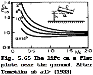 LIVE GRAPH
Click here to view rather cumbersome, as it involves doubly-connected regions. A much simpler approximate theory by I Tani et at, (1937), using the classical Bimbaum loading distributions, gives quite accurate results and significant errors appear only when h/c < 1/4. A summary of these kinds of investigations has been given by Y Hamal (1953). All these results show that the lift depends not only on the distance h/c from the ground but also on the angle of incidence: in some conditions, the lift is less than the free-air value, in others it is higher. What actually happens on a threedimensional wing must, therefore, be a rather complex interaction, especially during the landing flare, when the actual angle of incidence may change rapidly with time so that dynamic effects may matter. Therefore, we cannot yet fully explain why some particular aircraft will "land itself", presumably by generating the right amount of extra lift in the right place so as to provide the necessary deceleration and nose- down pitching moment, and why other aircraft do not. To design aircraft from the outset which have the desired safe behaviour during this manoeuvre is as yet beyond our means.
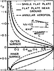
An explanation of the sectional lift changes near the ground has been given by J A Bagley (1959) by calculating the pressure distribution over a twodimensional flat plate. An example is shown in Fig. 5.66. Similar results have been obtained by V Losito (1972). We find that the effect of the ground on the
LIVE GRAPH
Click here to view flow is such that the lift is reduced over the upper surface and increased over the lower surface so that the overall lift depends on how this balance works out. Evidently, as the wing approaches the ground, the mass flow that
|
passes through between wing and ground is reduced and hence the pressure increased, and so there is eventually an overall gain in lift on a twodimensional aerofoil section. The sectional lift slope is, therefore, a highly nonlinear function of h/c and a. We digress here to point out that this flow is closely related to that past annular aerofoils (see e. g. D KUchemann (1941), D KUchemann & J Weber (1943), J Weissinger (1956), J A Bagley et al. (1958)).
As can be seen from the example in Fig. 5.66, the effects are similar but even more pronounced on annular aerofoils because of the threedimensional nature of the flow.
It is tempting to try to estimate the ground effect by representing the wing not by a continuous distribution of vorticity, as in Bagleyfs theory, but by a single "lifting line". That this leads, once again, to completely misleading conclusions has been shown by E C Maskell (1960, unpublished) who, at the same time, clarified the important effect that the ground has on the pressure distribution due to thickness. He considered the instructive case of inviscid, incompressible, flow past a circular cylinder in the presence of the ground and showed that a pair of circular cylinders, without circulation about either, can be represented exactly by two sets of doublets in a uniform stream, of strengths у, situated at a radial distance r from the centre of each unit circle, with their axes normal to the radius vector r, together with their reflections in the circle, of strengths y/r2 , situated at the inverse point at radial distances 1/r from the centre of the circle. Each set has, as its principal member, a doublet of strength у – 2ttV0 at the centre of a
![]()
![]() Succeeding members diminish in strength in the se-
Succeeding members diminish in strength in the se-
![]() 2ttV,
2ttV,
(5.34)
Г – —,
and are displaced from the centre of one cylinder in the direction of the other in the sequence
Each cylinder can be given a circulation Г around it, if line vortices are so placed as to be at the inverse point of either circle, that is to say, they must be placed at the radial distance Гр from the centre of each circle in the direction towards the ground, such that
The resulting tangential velocities around the cylinder induced by the doublets and vortices can then be calculated. By applying a form of Kutta condition, the circulation Г can be chosen to make the overall tangential velocity zero at a certain circumferential angle a, as indicated in Fig. 5.67.
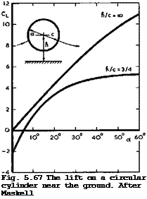 LIVE GRAPH
Click here to view
The lift is determined by integrating the pressures, and typical results are shown in Fig. 5.67. When the attachment and separation points are located opposite to each other (i. e. when a = 0 in Fig. 5.67), then the cylinder is attracted towards the ground. There is then one condition, with circulation, when the cylinder experiences no force. For greater circulations, there is a lift force on the cylinder. It will be seen that the lift is a highly nonlinear function of a and that the ground effect is so strong that CL reaches a maximum value even in inviscid flow: thickness effects combined with circulation may be so powerful that the flow of air between the body and the ground is completely stopped.
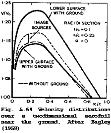
J A Bagley (1959) has shown how these effects manifest themselves on а Ыггек
lifting aerofoil in a twodimensional inviscid flow. Even a thick aerofoil at zero angle of incidence causes an asymmetric flow with circulation near the ground, as can be seen from the example in Fig. 5.68. Source and vortex distributions along the chord are needed to represent the aerofoil. Unlike the
 LIVE GRAPH
Click here to view flow past a flat plate in Fig. 5.66, the flow due to thickness generates the higher velocities on the lower surface and the lift is negative, i. e. directed towards the ground. Bagley*s method can deal with general section shapes and the results have been found to compare well with experimental results. The method is of a kind that can readily be incorporated into the framework of the RAE Standard Method. It has not yet been extended to threedimensional wings.
In view of the rather drastic changes in the pressure distribution which the ground effects cause, we must expect that the stalling of wings may also be affected. In particular, it is possible that the type of stall may switch over from one to another (see Section 4.7, Fig. 4.39), especially if the wing is close to the borderline between two types. This interaction is so complex that values of С^шх cannot yet be predicted with confidence in given cases. In general, the ground effect is unfavourable on sweptback wings of high aspect ratio with powerful high-lift devices. In view of this, the information needed will often have to be supplied by experiments. But such tests have their own problems. If a special board is provided to represent the ground, a circulation will, in general, be generated around it, that distorts the flow to which the model is exposed. To prevent this, J A Bagley (1959) added a sharp leading edge to the ground board, with pressure tappings above and below it. A flap at the trailing edge of the ground board was then deflected until the pressure readings were the same, indicating that at least the attachment streamsurface would lie along the leading edge of the board. Even then, a boundary layer will develop along the ground board in what might be a strong adverse pressure gradient (see e. g. Fig. 5.66). As long as the boundary layer does not separate, its displacement thickness may be calculated from the measured pressure distribution over the ground, say, as proposed by L F East (1970), and the actual distance between model and ground corrected accordingly. Another step further would be to apply boundary-layer suction over the ground board. Separation might thereby be prevented, in principle, but the
problem is then to adjust the suction rates everywhere in such a way that the associated sink effect does not distort the flow. Yet another step further is to move the ground surface along in its plane at a speed which simulates in the windtunnel the correct relative speed between the aircraft in flight and the ground. This can be done by means of a moving belt, which is mechanically complicated but has been accomplished successfully, e. g. by S F J Butler et al.
(1963) , J Williams & S F J Butler (1964), and T R Turner (1967). The latter has provided a rough criterion for conditions when a moving ground is needed, namely, when the value of the parameter C^/(h/2s) exceeds about 20. An excellent review of these and other testing techniques has been given by Ph Poisson-Quinton (1968).
We turn now to the flows near the junctions of intersecting wings. That such intersections might cause strong disturbances and high "parasite drag" forces was recognised early on when wings were supported by struts which might cross each other (see e. g. M Kohler (1938)). Now we find such intersections mainly between fin and tailplane.
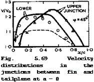
Consider first what happens when two identical wings without lift and without sweep intersect at right angles to each other. To a first order, we may expect that the two flowfields can be superimposed so that the velocity increment along the junction should be twice that of the wing alone. However, thinking of each wing as being represented by a distribution of sources, we recognise that this simple addition implies that the volume which the two wings have in common is represented twice. A source distribution corresponding to this volume should, therefore, be subtracted*) and the velocity increment along the junction will then be somewhat less than twice the individual contributions. This is borne out by experiments, as shown by the example in the upper part of Fig. 5.69 (from tests by D Kiichemann & J Weber (1948)). The full line corresponds to the simple addition, and the measured velocity level is below that by an amount which is roughly the same as that induced by a source distribution representing the common volume (which may readily be calculated) . The experiments also showed that the interference effect fades out with distance away from the junction like the flowfield of the interfering wing. Roughly, the velocity increment reaches that of a single wing at a distance Ду = c/2.
Consider now what happens when one or both wings are swept, as in most practical cases. In accordance with the concepts developed for wing-fuselage interference, we must expect that the main effect will be that one wing acts as a reflection plane to the other. Thus kink effects will come in, in addition to the superposition of sheared^wing velocity increments, as in (4.86) for single non-lifting wings. These kink effects may again be regarded as additive, to a first order. For example, consider two intersecting wings: a sweptback tail – plane and a sweptback fin at zero lift, sweep angles, section shapes, and wing chords being the same. Along the lower junction, the fin behaves as though it has a sweptforward kink, owing to its reflection in the tailplane; whereas the tailplane by its reflection in the fin behaves as though it has a sweptback kink. Thus the two kink effects should cancel one another, leaving only two sheared-wing terms to be added (minus the source term from the common volume, as before). Along the upper junction, both fin and tailplane should exhibit sweptback kink effects, which should thus be added together.
■’This is, of course, basically the same concept as that of the "source method" for estimating wing-fuselage interference, as discussed in Section 5.6 .
Again, this simple argument is borne out by experiments, as shown by an example in the lower part of Fig. 5.69 (from tests by D KUchemann (1948)). The full lines have been calculated in the way just described and evidently represent the overall trends quite well.
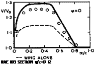 LIVE GRAPH
 |
Click here to view
These principles – superposition and reflection – may be applied quite generally. Lifting wings can also be treated in this way. The same principles may also be applied to other more complex configurations, such as struts or stores attached to wings. In all such junctions, flowfields may be superposed and kink effects will appear if any of the members are swept. But the results cannot be expected to be very accurate, especially near the leading and trailing edges where such a simple theory cannot represent details. Panel methods cannot be expected to be very accurate either, unless the reflection behaviour is properly incorporated, as explained in connection with Fig. 5.43. Also, there will be strong but as yet largely unknown viscous effects in the junctions. Thus, for the time being, only the main overall features of the flow past intersecting wings can be determined.
These large interference effects between intersecting wings pose a severe design problem. The high local velocities and the possible loss of effective sweep lead to low critical Mach numbers which, in general, cannot be tolerated. For swept fin-tail combinations, the design can be made somewhat easier from the outset if fin and tail are separated by a fuselage, or if a swept – back tail is put on top of a sweptback fin. As explained above, the two kink effects then roughly cancel each other, at least along the lower junction.
Such cancellations occur quite generally when one wing, if folded around the intersection line into the plane of the other wing, forms a continuation of it. Even so, a difficult design problem remains if the aim is to derive the full benefit from sweep, i. e. if the isobars on all surfaces should at least be fully swept everywhere, following the design principle illustrated in Fig. 5.1 (b). One way of achieving this is to add a separate body between the intersecting surfaces and to shape the new junctions suitably. Such threedimensional bodies must be expected to have deep indentations to bring
Next Page
about the required large reductions and changes in the (basically twodimensional) velocities in the manner of the sketch in Fig. 5.54. Thus these bodies will have to be fairly wide to begin with, where they intersect the leading edges of the wings. This implies, in turn, that the fairing must have a correspondingly long forebody so that its own self-induced velocities are not too high. Such a design may, therefore, end up with a rather large body and consequently a significant additional skin-friction drag. But the volume provided by the fairing may often serve some other useful purpose.


Fig. 5.70 Shape of a fairing in the junction between a sweptback fin and a sweptback tailplane. RAE 103 sections; t/c = 0.12 ; <p = 45°
A typical shape of such a fairing between intersecting fin and tail surfaces is shown in Fig. 5.70 (from a design by D Kuchemann (1948)). This fairing has local bulges in front of the leading edges so that its thickness there is four times the wing thickness. The junction shapes were designed to compensate for the various interference velocity increments, discussed above, using a quasi-cyliiider theory described in Section 5.6 and making small empirical adjustments. Inspite of the obvious shortcomings of such a theory, the fairing shown in Fig. 5.70 did produce fully-swept isobars on all the fin and tail surfaces at zero lift and also at a moderate lift on the tail – plane, at low speeds. The different shapes needed in the different junctions demonstrate clearly the nature of the different interference effects. A reliable theory for designing general fairing shapes of this kind has not yet been developed.
Actual fairings between fin and tailplane are often designed as a compromise allowing, for example, for flat surfaces required to prevent gaps on an allmoving tail. We note in this context that even partial fairings as opposed to complete fairings of the kind illustrated in Fig. 5.70, may bring some benefit. D E Hartley (1953) has shown, for example, that a rear fairing alone, much like the rear part of the fairing in Fig. 5.70, may effectively postpone the occurrence of severe buffeting to higher Mach numbers by breaking up strong oscillating shockwaves near the trailing edges of fin and tail, in a manner similar to that of rear bodies sketched in Fig. 5.27. The first successful application of such a rear fairing was to the tail of the Hunter aircraft by Sir Sidney Camm (see e. g. A P Cox & D A Kirby (1952)).
The interference phenomena discussed so far are undesirable nearfield side
Previous Page
effects of the main purpose of the fin-tail assembly; to produce required lift and side forces. These depend very strongly on the actual configuration. Although, on present knowledge, an adequate theory for designing fin – tail combinations to give the required, loadings could be developed, such a design theory does not yet exist. We are concerned here always with nonplanar lifting systems, in an upwash or in a sidewind, and it is, therefore, not surprising that the Trefftz plane concepts have often been applied to calculate the properties of systems which give minimum vortex drag, when the induced downwash in the Trefftz plane is assumed to be constant along the span. Such non-planar combinations have been investigated by К Mangier (1938), V M Falkner & C Darwin (1945) and D Kuchemann & D J Kettle (1951) for wings with endplates. In the present case, such endplates can serve a useful function as fins, which an equally effective extension of the span could not (see Section 3.2). J C Rotta (1942) has calculated the properties of wings with single plates; J Weber (1952) and (1954) those of wings with fences, of fin – fuselage, and of wing-nacelle arrangements; and J Weber & A C Hawk (1954) those of fin-tail-fuselage combinations. We mention here also the work of D E Hartley (1952) on wings with tip tanks, which deals with a similar problem.
|
|
|
Cyc/0t |
|
Cyo/0=19 Cy/Cy0=l-9 |
|
Cy/Cy0=22 |
|
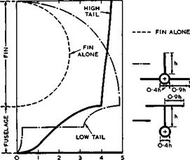
Fig. 5.71 Distributions of the side force on fin-fuselage-tail combinations in sideslip |
Typical results of such calculations are shown in Fig. 5.71. We find that fin-tail-fuselage combinations are much more effective in generating a side- force than the fin alone would be; A low-tail configuration produces 1.9 times the side force of the fin alone, and a high-tail configuration 2.2 times that of the fin alone. In this respect, the interference between fin and tailplane is very beneficial.


