LIFT OF SWEPT WINGS
|
Г"* |
![]()
![]()
![]()
![]()
It must be noted, however, that because of wind-tunnel interference, values higher or lower than indicated can be found in various references. For practical purposes, equation (33) is suggested to be sufficiently accurate. It shows that the sectional lift angle is as indicated by equation (31). For example, for M = 0.9, and j/4 = 35 as in the F-86 fighter airplane (24) the two-dimensional pa rt of the lift angle is reduced, as against conditions in incompressible fluid flow, by some 3° . In spite of the angle of sweep (increasing the lift angle by almost 2° ) the lift-curve slope is increased in this example. The reduction of the angle due to compressibility amounts to some 5° , from that of the same wing (with A = 4.8) in incompressible fluid flow, in the order of do/ /dCL = 14° ; the result is do6 /dCL = 11 , or = 10 , when considering the influence of the fuselage. This result agrees with flight-test and full-scale wind-tunnel data reported in (24).
LARGER ANGLES OF SWEEP. Evaluations similar to that in figure 22 can be made for different aspect ratios and angles of sweep. On the basis of equation (21) it can be expected that the lift angle may be increased by a component proportional to l/cos2J . Figure 23 exhibits a single point for A = 522 and M = 0.8, showing about 60% of the increment as given by the equation. It is suggested again that viscosity (boundary layer accumulation on the wing tips) is responsible for the deterioration of the few experimental points at angles of sweep between 50 and 60° (see also figure 24). In fact, atV = 60 , where cos7 = 0.5, the effective thickness ratio of the wing sections (in the direction normal to the panel edges or axes) is twice that of a straight wing. The boundary layer is also increased in thickness by the velocity component (V sinV) along the panels. The type of flow pattern thus developing will be further discussed in Chapter XVI.
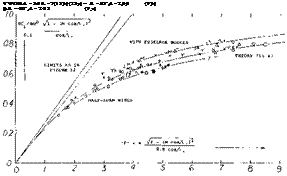
ASPECT RATIO. Disregarding the possible influence of viscosity (creeping flow separation in larger angles of sweep, as above) the most suitable lift formulation, for swept wings with aspect ratios between zero and infinity, is as in (11,a) similar to that in figure 12. Experimental
results in figure 24 do not readily confirm the theoretically expected lift-curve slopes. The spread is up to + 10% and — 5%. Examination of the experimental conditions leads to the following statements:
a) In combination with fuselages, lift is markedly increased. Using equation (22) a body diameter d = 0.2 b would explain a 10% increment.
b) There are several inconsistencies in the data plotted. It can be assumed that wind-tunnel blockage or other test conditions are responsible.
c) The points evaluated from tests in (25,a) show good correlation between a 47 7 swept and an essentially straight wing.
d) As in figures 12 and 20, half-span wings have low lift coefficients. However, when tested on a bump, their lift is on the average as high as expected by theory.
e) Reference (25,b) although affected tunnel blockage, gives a comparison between wings swept to plus and minus 35 and 45 . Correlation as shown in the graph was only obtained, however, after changing the consequence of equation (20) into
A A°= — 25/A
о VARIOUS SOURCES (23)
do<г/dCL x A = 3.5, CORRECTED (23,b)
+ A = 4, CORRECTED (22, g)
Л =. 45° + 52°
20-
Л.= 60°
M = 1.0
da^dC^ *10 j – (M cos/t+)2/cos/+
doCi/dCL = 20/3 = 7° //COS A
. i___ і__ і___ j___ l___ і___ і___ і_ 1 … – Ti—
‘0 .2 4 .0 – S /0 /2 !A f£ i. Q 2.0
![]()
Figure 23. The lift angle of swept-wing-fuselage combinations with A = 3, and M cos =0.5.
CRITICAL MACH NUMBER. As discussed in Chapter VII, the critical Mach number is theoretically that at which at some point, usually at the upper surface of a lifting wing, the local velocity is equal to the sonic speed. Upon exceeding the critical Mach number, forces and moments are likely to show variations different from
(25) Subsonic characteristics of various swept wings:
a) Silvers, Wings With Missiles, NACA RM L54D20.
b) Whitcomb, Wing Plus/Minus 45°, NACA RM 46J01a.
c) Sutton, With Body Contouring, NACA RM A1956J08.
d) Goethert, Lil’thal Rpt 156 (1943); NACA TM 1102.
![]()

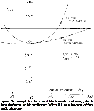
 those at lower speeds. According to the cross-flow principle of swept wings, the sonic speed first to be encountered in their panels corresponds to M = 1/cos. A, where Л may be equal to 7^. , determined as per equation (20) or (35). Considering, however, a reduction of the critical speed due to thickness (say t/c = 9%) at some small lift coefficient (say CL = 0.1) the corresponding Mach number would be in the order of
Mcr. it = 0.77/cos A (36)
It is seen in figure 23, how this upper number can grow into the supersonic range. At – Л+= 40 , the critical number in the wing panels is M = 1, in the example considered.
a) WING-BODY COMBINATIONS
I A = 4, A = О b 35° (22,b)
+ A = 4, A = 45° (10,a)
x A = З, И = 19,45,53° (23,d)
a A = 4, A = 4° (25,a)
» DITTO, A = 47° (25,a)
л A = 6, A = 35° (28,c)
H A = 4, A = 45° (22,d)
Y A = З, b = 6 (29,e)
Figure 24. The lift-curve slope of swept wings at Mach numbers between 0.4 and 0.9, as a function (16,a) of the aspect-ratio parameter “F”.
(26) Pressure distribution across the span of wings:
a) Neumark, Critical M’Number, ARC RM 2821. Transonic similarity as in this report also in Chapter XV of “Fluid Dynamic Drag”. See also ARC RM 2713 & 2717.
b) Kuchemann, With W’out Body, ARC RM 2908 & 2935.
c) Holmes, 40° With 10% Sections, ARC RM 2930.
d) Weber (RAE/ARC), Symmetrical Sections (RM 2918), Cambered Sections (RM 3026), Centre Part of Wing (RM 3098); also J/RAS 1959 p 476.
e) Cook, Comparison at High Speeds, ARC RM 3194.
0 Runckel, 45° 65A004 Transonic, NASA TN D-712.
g) See also the chord wise distributions under (5).
h) Bagley, Calculated, ARC C’Paper 675.
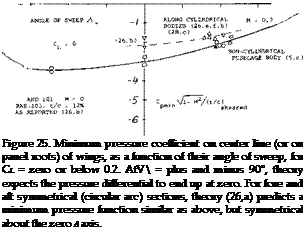
CENTER OF A SWEPT WING. In the center of a swept wing there cannot be a cross flow. As explained in (26,b) the supervelocities along the center line of a swept-back wing are usually lower than in the wing panels, when considering conditions at zero lift. The low-speed minimum pressure coefficient in the wing center is plotted in figure 25, particularly for 12% thick RAE sheared foil sections (26,b) as a function of the angle of sweep. The flow around and over the apex of a swept-back wing is more or less three-dimensional. However, as a consequence of the flow components converging onto the center line, from the swept-back wing panels, quasi-two – dimensional conditions are obtained along most of the way toward the trailing edge of the center part of the wing. In other words, we have to deal with the full speed
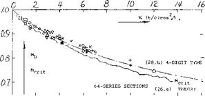
V. Taking up the example again as in connection with equation (32), figure 22 indicates for J = 40 , at low speeds, an average C p = — 2.1 (t/c) = — 0.19. Using figure 2 of Chapter VII, the critical Mach number in the center of the wing is then M = 0.83. This value is appreciably higher than that of a straight wing having the same airfoil section; M crit = 0.77. The two critical M’num – bers are shown in figure 26 as a function of the angle of sweep. Points derived from pressure distribution data (26,b) agree with transonic similarity theory (26,a) after taking into account the difference between “sheared” and “yawed” thickness ratio. It must be remembered, however, that reaching the critical M’number does not yet mean a divergence of forces. Drag-divergence Mach numbers of swept-back wings for zero (or sufficiently small) lift coefficients are plotted in figure 27, using the correlation as in (28,b). These numbers can be some 5% higher than the critical values. The graph suggests that the delay of divergence (but not the divergence Mach number as such) increases with the thickness ratio t/c.
-66 -40 -го о го 40 oo’
 WING ROOTS. Considering conventional airplane configurations, there is necessarily a fuselage covering the center area of a swept wing. As demonstrated in “Fluid Dynamic Drag”, whatever is done to the shape of slender bodies their critical speed is below M = 1, say at M = 0.95. Subsequently, they are exposed to supersonic velocities along their surface, and recompression becomes deficient. Regarding the interference with the two panels of a swept wing, theoretical and experimental results reported in (26) indicate that the panel roots adjoining a more or less cylindrical fuselage body, exhibit at zero lift, approximately the same pressures and distributions as described above for the center line of a wing alone. A few wing-root points are included in figure 25. In fact, in a particular configuration (23 ,f) the wing root thickness can be increased to critical or divergence Mach number (at zero lift). This result will change, however, at positive lift coefficients (say above 0.2) where the wing roots are bound to become more critical in the two-alpha flow induced by the fuselage. Also, considering the supervelocities along curved fuselage shapes, pressures along the wing roots must be expected to be lower than in the panels.
![]()
![]()


![]()

a) WITH FUSELAGE, WING ROOTS
о (10,a)(22,e) (25.a) (28,a) □ (23,d, e)
■ (23,f)
$ (22, b)
A OTHERS
b) HALF SPAN ON BUMP
о (25,b) x (28,b)
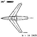
Figure 28. Example (28,c) of fuselage contouring, intended to increase the critical or force-divergence Mach number of swept wings. The indentation is shown along the wing roots as a pair of heavy lines.
CONTOURING (29). Figure 28 shows how suitable contouring of the fuselage walls (similar to that according to the transonic area rule) makes room for the typical panel cross flow to develop. The critical Mach number of the wing roots may thus be increased, from the lower boundary as in figure 26 possibly to the supersonic values as in
(27) Nelson, Straight Wings on Bump, NACA TN 3501, 3502.
 sufficiently swept panels. The fuselage retains its critical subsonic Mach number, however. Critical flow conditions of any swept wing, or wing-fuselage combination, are thus always reached below M = 1. By suitable contouring or shaping according to the transonic area rule not a subject of this text, but see (1) for example expansion, recompression and shock formation along the body may be kept harmless. As an example (26,b) pressure coefficients on the roots of a wing with t/c = 12%, at CL = zero, and at low speeds, are quoted as follows:
straight wing with cy lindrical fuselage same wing with contoured fuselage in panels of 45 0 sheared wing roots of 45° wing with cylindrical body roots in presence of contoured fuselage.
In case of a lifting wing (to be discussed below) contouring can be applied above the wing roots (2,c) thus making room for the converging streamlines at the upper side. As shown in (29,d) a similar effect is obtained when placing the wing panels on top of the fuselage (high-wing).
FUSELAGE INTERFERENCE. At an angle of attack, the roots of any wing (straight or swept) are considerably affected by the fuselage. As explained in Chapter VIII of “Fluid Dynamic Drag and Chapter XX, any cylindrical body produces a two-alpha flow, resulting in upwash at the wing roots. As a consequence, pressure distributions as in (26,f) and (29,a, b) exhibit peaks near the leading edge of the panel roots beginning at C = 0.2 in a symmetrical, and at C = 0.4 in a 5% cambered section (5,c). Aided by the spanwise boundary-layer flow (described in Chapter XVI of this text) lift coefficients on the wing roots can thus be very high, say twice as high as in the remainder of the panels. In thin and symmetrical wing sections, these pressure peaks are cut down considerably by laminar separation. As shown in (26,f) and (29,b) the load distribution, as in figure 6, is nevertheless filled up to an essentially elliptical shape; and this fuselage effect is the reason for increased lift-curve slopes mentioned in connection with figures 13 and 24. Wing-root pressure distributions (29) vary corresponding to section thickness between 3 and 9%, and camber between 0 and 5% of the chord. Minimum pressure coefficients differ considerably, and it is impossible to find any reasonable correlation. It can be argued, however, that local supersonic “spots” developing on the wing roots at higher subsonic Mach numbers will not have any noticeable influence upon flow pattern and lift of swept-back wing-fuselage combinations. Disregarding, therefore, these peaks the minimum pressure coefficients found around 40% of the root chords of swept-back wings, may be said to be in the order of
Cpmm = – 2 (t/c) cos2W — KCL (36)
where CL = average wing coefficient, and К in the order of 0.4 for symmetrical sections with t/c = 4%; about twice that high for t/c = 7%; and up to 1.2 for properly cambered root sections. Thin and sharp leading edges thus lead to more or less local separation, while rounded and cambered sections permit the two-alpha flow to produce high lift with extended low-pressure areas developing on the wing roots.
CRITICAL LIFT. As suggested in (26,a, b) the full speed V, and the Prandtl factor as in figure 1 of Chapter VII, have to be considered in the center or on the roots of a swept wing. Therefore:
Cpmm" C p mine/ JT~—~М~г (37)
where C p mine = incompressible coefficient, for example as in equation (36). It should be noted that the pressure coefficient on the wing roots grows as a function of Mach number, at a higher rate than any coefficient in the swept panels (as in equation 36, or as shown implicitly in figure 26). For statistical purposes (as in figure 29) it is suggested to use К = 1, in the last equation. As explained before, a subsonic flow pattern can be maintained in the panels of swept wings, say between 0.3 and 0.9 of the half span, at lift coefficients below 0.1 or 0.2, up to Mach numbers in the order of (0.8 cosy). For example, it is demonstrated in (28,e) that the cosine principle still holds at a Mach number of 1.2, in the outboard 75% of the half span of a sufficiently swept-back wing, at or near zero lift. Flowever, when really lifting, a negative pressure ridge appears in the wing panels, near their leading edges, when using essentially symmetrical wing sections. As shown in figure 6 of Chapter VII, it is statistically and approximately (for low lift coefficients, and at low speeds):
Cp mm =-C * /(t/c) (38)
In the panels of a swept wing, we have to substitute, Corresponding tO the COSine principle: (Cpmtn /cos2A ) for (CP mm ); (Cu /cos*LA ) for (CL); (t/c)/cosЛ for (t/c); (M cos7) for (M). Equation (38) thus reads, for a sheared wing:
CPm(n/cos2A = (Cl/cos2A)2′ cos A/(t/c) (39)
(28) Flow and forces above critical M’number:
a) Whitcomb, 65A006 / A = 4 / 45°, NACA RM L1952D01.
b) Polhamus, Transonic Bump Results, NACA TN 3469.
c) VonKarman, Similarity, J Math Phys 1947 p 182.
d) Ackeret, Swept High Speeds, NACA TM 1320.
e) Bagley, Shape and Drag, ARC C’Paper 512.
![]()
![]() Using the Prandtl factor corresponding to /l — (M cos./if (see figure 1 of Chapter VII) the critical Mach number (M cosA) is then found in figure 2 of the same chapter for (C p min /cos2_A ). Confirming the procedure, a set of experimental points obtained on a 45° swept wing, was reduced to A =0, and included in figure 6 of Chapter VII. The result is of the same type as the upper boundary in figure 26. This means that the critical number M cm = (M cosA)/cosA, can still be supersonic. As an example, a wing with t/c = 9%, and A = 40 , was evaluated regarding critical Mach number. As shown in figure 29, the critical number in the wing panels is highest at lift coefficients below 0.25. In fact, the permissible speeds remain supersonic up to CL slightly above 0.15. Within the range of smaller lift coefficients, force divergence is first caused by high speeds (low pressures) on the wing roots. We have plotted a line using К = 1 in equation
Using the Prandtl factor corresponding to /l — (M cos./if (see figure 1 of Chapter VII) the critical Mach number (M cosA) is then found in figure 2 of the same chapter for (C p min /cos2_A ). Confirming the procedure, a set of experimental points obtained on a 45° swept wing, was reduced to A =0, and included in figure 6 of Chapter VII. The result is of the same type as the upper boundary in figure 26. This means that the critical number M cm = (M cosA)/cosA, can still be supersonic. As an example, a wing with t/c = 9%, and A = 40 , was evaluated regarding critical Mach number. As shown in figure 29, the critical number in the wing panels is highest at lift coefficients below 0.25. In fact, the permissible speeds remain supersonic up to CL slightly above 0.15. Within the range of smaller lift coefficients, force divergence is first caused by high speeds (low pressures) on the wing roots. We have plotted a line using К = 1 in equation
(36) . In conclusion, the cosine principle (being the foundation of swept-wing design) does not necessarily prevent supersonic velocities and their consequences (drag, shocks, buffeting) along the wing roots. However, contouring of the fuselage body as described above can possibly produce a flow pattern over the upper side of the wing roots, similar to that in the wing panels. Even then, the body itself is bound to retain a subsonic critical Mach number (say M = 0.95); and the body will pay a penalty (say at M = 1, by supersonic expansion, recompression through a shock, and drag) for letting the wing remain subcritical.
FORWARD SWEEP. The most interesting fact to be noted in figure 25 and 26 is the sensitivity of the center of swept-forward wings. As shown in (12,e), the minimum pressure on center line (at zero lift) is approximately:
Cp fr>iг) = — 0-25, atx/c = 0.37, in center 45° swept-back = – 0.27, at x/c = 0.25, average in wing panels = — 0.60, at x/c = 0.03, center 45° swept-forward
It is thus seen how the swept-forward panels induce considerable supervelocity near the leading “edge” of the wing center. This situation becomes even more pronounced when lifting. As shown in figure 6, lift and lift coefficient are concentrated in the center of a swept – forward wing. Experimental results reported in (I2,e) indicate peaked minimum pressure coefficients near the leading edge of the center of a 30° swept wing, roughly as follows:
Cpmir, = – 0.3, for swept-back panels
— 0.6, for the straight wing
— 1.2, swept-forward panels.
Conditions of the tunnel tests were as follows:
wing yawed 30 from yawed airfoil section lift coefficient approximately Mach number of testing
Although the result cannot be generalized, the value of Cpmm in the center when swept-back is in the order of half of that for the straight wing and twice that high in the swept-forward condition. The corresponding critical Mach numbers at the center (or on the wing roots) are in the order of
M CRJT = 0.8, for yawed-back panels = 0.7, for the straight wing = 0.6, for yawed-forward panels.
In conclusion, the swept-forward type of wing is not promising in regard to critical speed. It must be said again, however, that forces do not necessarily diverge at The critical Mach number. The drag coefficient in the roots of the wing just quoted is only CD = 0.015, at M = 0.8, in comparison to 0.008 in the panels. It is also interesting to note that the center of a 45 swept-forward wing tested (12,g) at low speed, stalls at C L = 0.5, while the lift-curve slope continues to CL =0.7, and the maximum is C Lx =
1.0. Similar conditions are seen in figure 8. Local drag coefficients at the wing roots can then (12,e) be up to 10 times as high as in the panels.
ENGINE NACELLES. When the engine nacelles is built into the panels, the interference effect upon swept wings is similar to that of a fuselage. In fact, in a swept-back wing the inboard junctures (corners) have a flow pattern similar to that in the center of a swept-forward wing. Low pressures are-concentrated in a peak near the leading edge. This condition is aggravated at any lift coefficient different from zero or “symmetrical” (see Chapter II). Even without the help of compressibility, flow separation (as in part (b) of figure 8) is easily encountered. As an example, pressure distributions around an engine nacelle (16,a) installed in a 35 swept-back wing, with 12% sheared sections, show at = 0.3, peaked minima at the inboard side, more than twice as high as in the outboard corner.
(29) Pressures along roots of swept wings:
a) Mugler, Wing + Body, NASA Memo 10-20-1958L.
b) Cassettim 53° Swept Transonic, NASA TN D-971.
c) McDevitt, Body Contouring, NACA RM A1955B21.
d) Dickson, Wing-Fuselage Height, NACA RM A55C30.
e) McDevitt, Investigation of Fuselage Contouring on Wing – Body Combinations, NACA RM A1957A02.
0 Contouring first tried at DVL (4)(25,d)(26,b).
By comparison, the critical Mach number in the particular configuration tested would be Mcrit = 0.6 outboard, but below 0.5 inboard. Another example (21 ,c) with 45 sweep, using 65A006 sections, shows at CL = 0.3 a drag divergence number Mq = 0.96 without nacelles, and M = 0.92 with nacelles. Some creeping divergence is evident, however, beginning at M = 0.8.
HIGH-SPEED PERFORMANCE. From what is said in this section regarding critical Mach number it can be concluded that the gain in maximum cruising speed of airplanes through the use of swept wings is limited, see figures 26 and 29. Modern airliners may, on the average, be operating as follows:
having an aspect ratio A = 7, with some 30 of sweepback, cruising at coefficient C L =0.3, at an altitude of 9 km, 30,000 ft. critical Mach number below 0.8, maximum M’number, approaching 0.9.
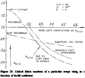 If their speed is up to 1000 km/h (some 600 mph, oi above 500 knots) that must be compared with some 700 km/h (or less than 400 knots in the previous generation of (straight-wing and propeller-driven) transport airplanes. Upon inspecting figure 26, it can then be concluded that the increase of cruising speed was brought about not just by sweepback, but also by jet propulsion. In aerodynamic respect, consideration of range (as in Chapter I) would call for a cruising lift coefficient in the order of 0.35. As indicated in figure 29, the critical Mach number for this coefficient might only be between 0.6 and 0.7. On the basis of experimental results such as in (26,c) for example, the permissible coefficient for M = 0.8 may be noticeably higher than indicated by MCRlT, say at least CL = 0.3 . A weak and evidently harmless shock front can be seen across the wing panels (under favorable conditions of sunlight) by airline passengers prepared for the phenomenon.


