PRELIMINARY CONSIDERATIONS, PRIOR TO ESTABLISHING NUMERICAL SOLUTIONS
Prior to establishing a numerical solution, some of the options need to be considered:
Type of singularity that will be used
The options usually include sources, doublets and vortices or any combination of the above.
Type of boundary conditions
Velocity or velocity-potential formulation may be used and the corresponding Neumann, Dirichlet, or a combination of such boundary conditions must be selected.
Wake models
How and where the Kutta condition will be specified. Also the shape of the wake is controlled by Eq. (9.18a) and can be set by:
1. Programmer specified shape based on intuition or on flow visualizations.
2. Wake relaxation (where the wake points are moved with the local induced velocity, e. g. in Ref. 9.2).
3. Time stepping (where the wake shape is developed by moving the wing from an initial stand-still position, as will be presented in Chapter 13).
Method of discretizing surface and singularity distributions;
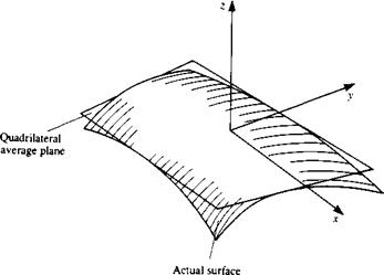
1. Discretization of geometry. The placing of a simple panel element on an arbitrary three-dimensional configuration is rather difficult. Figure 9.11 describes such a curved surface element with a local coordinate system x, y, z. The shape of the surface can be described as z = f(x, y), but for simplicity it is usually approximated by a piecewise polynomial approximation. For example, if a first-order polynomial is used then the average surface can be described by
z = a0 + b1x + b2y
and for a second-order polynomial approximation
z = a0 + biX + b2y + CjX2 + c2xy + c3y2

|
|
 |
|
|
|
|
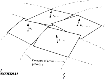
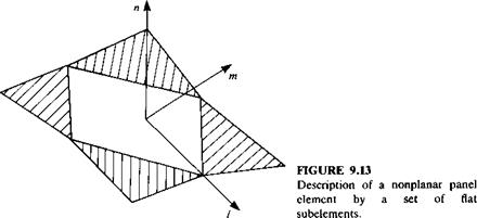
and so on (where the coefficients a, b, c are constants). Figure 9.11 shows the result of approximating a curved surface element by a first-order plane, while Fig. 9.12 shows the possible consequence of representing a three – dimensional curved surface by such quadrilateral elements. This representation of the geometry may result in difficulties in specifying the boundary conditions, since the “leakage” between the panels can weaken the satisfaction of the zero flow through the boundaries requirement. One possible solution is shown in Fig. 9.13 where the surface is described by five flat subelements (as in the PANAIR code9 3).
2. Discretization of singularity distribution. The strength of the surface distribution of the singularity elements can be represented, too, in terms of a piecewise polynomial approximation. For example, if the doublet distribution on the element of Fig. 9.11 is constant such that
Iu = a0 = const.
then this is a zero-order approximation of ц. Similarly a first-order (or linear) approximation is
H=a0 + blx + b2y
and a second-order (or parabolic) polynomial approximation is
ц = а0 + Ьгх + b2y + сгх2 + c2xy + c3y2
(Here the coefficients a, b, c, .. . are constants, too, and of course are different from the coefficients of the surface approximation).
Considerations of numerical efficiency
It is clear from the brief discussion on discretization that the computation of the influence coefficients (e. g., Eq. (9.21)) is elaborate. Many methods divide such calculations into near and far field where the far-field calculation treats the element as a point singularity (and not as a surface distribution). Typically, the near field is assumed if the distance to a point P is less than 2.5-5 times the larger diagonal of the panel. Because of the 1/r characteristics of the singularity elements, when r—> 0 the value of 1/r—therefore, when the point P is too close to the panel (or to a vortex line) cut-off distances are usually applied. (Only the aerodynamic aspects of the numerics are discussed here; other important aspects, e. g., the matrix solver efficiency, are not.)


