REDUCTION OF THE PROBLEM TO A SET OF LINEAR ALGEBRAIC EQUATIONS
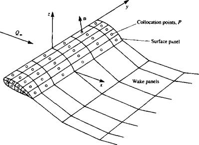
At this point it is assumed that the problem is unique and that a combination of source/doublet distributions has been selected along with a wake model and the Kutta condition. For the following example Ф* = Ф» along with Eq. (9.12) for the source strength will be used and a constant-strength rectilinear panel is assumed (this approach is widely used in many panel codes such as in Ref. 9.2). The body (see Fig. 9.7) is now divided into N surface panels, and into Nw wake panels. The boundary condition (either Neumann or Dirichlet) will be specified at each of these elements at a “collocation point” (which for the Dirichlet boundary condition must be specified inside the body where Ф,* = Ф«, e. g., at a point under the center of the panel). In most cases,
|
FIGURE 9.7 Approximation of the body surface by panel elements. |
though, the point may be left on the surface without moving it inside the body. By rewriting, for example, the Dirichlet boundary condition for each of the N collocation points, Eq. (9.11) will have the following form:
![]() -2 —f
-2 —f
к 1 4ТГ Jbody-panel кГ/
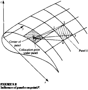
That is for each collocation point P (shown in Fig. 9.7) the summation of the influences of all к body panels and I wake panels is needed. The integration is limited now to each individual panel element, and for a unit singularity element (a or ц) it depends on the panel’s geometry only. The integration can be performed analytically or numerically, prior to this calculation, and, for example, for a constant-strength fi element shown in Fig. 9.8 the influence of panel к (defined by the four corners 1, 2, 3, and 4) at point P is
![]()
![]()
 and for a constant strength a element
 |
(9.21a)
These integrals are a function of the points 1, 2, 3, 4 and P and an “influence computing routine” can be schematically defined as
(Xp, yP, zP (9.22)
|
influence . * a a coefficient W calculation/ ‘ ‘ |
Xi, yt, zi
Хг, У2,*2 |ф
x3,y3,z3 I х4,Ул,24 I
Of course, in this case ЛФ/> = Ck. After computing the influence of each panel on each other panel Eq. (9.20) for each point P inside the body becomes
N Nw N
2 Ckfik + 2 С, Ці + X Bkak = 0 for each internal point P (9.23)
*=і /=i *=i
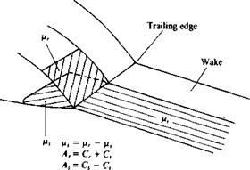
This equation is the numerical equivalent of the boundary condition. If the strengths of the sources are selected according to Eq. (9.12) then the coefficients Bk, which are computed in a manner similar to Eq. (9.22), are known and can be moved to the right-hand side of the equation. Also, by using the Kutta condition, the wake doublets can be expressed in terms of the unknown surface doublets pk. For example, in Fig. 9.9 two of the trailing edge (T. E.) doublets цг, jUj (here r, s, and t are some arbitrary counters) are related to the corresponding wake doublet fi, by Eq. (9.15),
V, = Pr~ Ps
and consequently the influence of the wake element becomes
С, ц, = C,(Hr – Ps)
This algebraic relation can be substituted into the Ck coefficients of the unknown surface doublets such that
A* = Ck if panel is not at T. E.
Ak = Ck ± C, if panel is at T. E.
 FIGURE 9.9
Relation between trailing edge upper and lower panel doublet strength and the corresponding wake doublet strength.
where the ± sign depends on whether the panel is at the upper or the lower side of the trailing edge (Fig. 9.9). Consequently, for each collocation point P, a linear algebraic equation containing N unknown singularity variables цк can be derived:
N
2 Akfik = – 2 Bkok (9.24)
*=i *=i
Evaluating Eq. (9.24) at each of the N collocation points (j = 1 -*N) results in N equations with the N unknown цк, in the following form:
|
|
|
all» fl12> a21» a22> |
 °m> aN2> ■ ■ ■ » aNN/ ^/V
Note that for evaluating the influence of the panel on itself {akk, bkk) the integral of the influence coefficients may be singular and its principal value must be evaluated. In this formulation the unknown ц distribution is small (perturbation only) and the numerical solution is believed to be more stable.9 2 The right-hand side of Eq. (9.25) can be computed since the value of ok is known and Eq. (9.25) can be rewritten as
«11 > a2> • • • » N / Pl / RHS,
|
Vrhs* |
![]()
«21» a22> • • ■ > a2N W P2 I RHSj
where the values of fJ. k can be computed by solving this full-matrix equation.
Also, the relation a = Q„ • n of Eq. (9.12) contains the information on the zero normal flow condition for the thickness problem and this formulation will be singular for surfaces approaching zero thickness.
The derivation of the influence coefficient integrals depends on the shape of the panel element (e. g., planar, curved, etc.), and on the singularity distribution (constant or linearly varying strength, etc.) and some examples will be presented in the following chapters.


