Some effects of non-uniform flows
In all the interference problems discussed so far, one part of the aircraft was placed in a stream which was disturbed but still irrotational and made non-uniform by the presence of another part of the aircraft in the neighbourhood. We now want to discuss briefly some flows where the non-uniformity in the stream is generated in a different way and leads to the presence of Vortioity somewhere in the flow past the aircraft part considered. Such flows are sometimes called non-
homenergic and, since most of the flows we shall deal with may be regarded as incompressible, the different energies in different parts of the stream correspond to different velocities and different total heads. Typical examples are wakes and jets, where the total heads are either lower or higher than in the mainstream. In many cases, the bodies are submerged in shear flows. Although some of the fundamental aspects have been clarified (see e. g.
W R Hawthorne & M E Martin (1955), W A Mair (1955)*; M J Lighthill (1957),
M В Glauert (1961)), there is as yet no satisfactory general theory for bodies in threedimensional shear flows. Here, we want to concentrate on some of the main physical effects that matter in aircraft design, which can be explained by considering inviscid flows past wings when there is a surface of discontinuity in velocity either in a horizontal plane or in a vertical plane. Further, we want to consider briefly some effects of time-dependent nonuniformities, such as atmospheric turbulence or gusts.
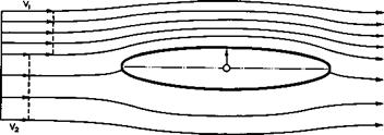
A very simple twodimensional non-uniform flow with a horizontal surface of discontinuity past a symmetrical body is shown in Fig. 5.72. In a uniform
|
Fig. 5.72 Flow past a symmetrical body in a non-uniform stream |
inviscid stream, the body would experience no force. When there is a discontinuity in the velocity profile upstream (and hence also in the total head, because there must be no pressure difference across the surface of discontinuity), we can readily see that the unseparated flow past the body with one attachment and one separation line will become asymmetrical (up and down, but not fore and aft), that a circulation will be built up around the body, and that a force will be exerted on it, which is directed towards the region of higher speed. This is a general physical feature of such flows, which can be generalised in the manner indicated in Fig. 5.73 to explain, for example,
|
Fig. 5.73 Direction of lift induced on a wing in non-uniform streams |
the lift forces acting on a thick tailplane at zero angle of incidence in, or in the neighbourhood of, wakes or jets. There is one reservation however:
* This work is specifically concerned with the effects of a spanwise velocity gradient generated by a boundary layer wake running over a wing. It is thus relevant also to the junction effects discussed in section 5.6 in connection with Fig. 5.45.
such a circulation and such a force can be built up only when the ICutta condition can be applied at a ‘trailing edge’ and if no other flow separations occur. If a flow separation does occur, as for example on a blunt-ended rear body, so that there are two separation lines, the resulting thick wake is likely to be asymmetrical and could lie on the suction side only (i. e. on the upper surface of the body in Fig. 5.72), and then the circulation and the sign of the force might be reversed.
We note at this point that the actual forces on a tailplane, say, in such a flow depend also on the local dynamic) head. Thus the load on a tailplane is reduced when it is moved into a wake region with lower velocity. This explains the presence of a tailplane efficiency factor in (5.29) and
(5.30).
Shear flows with gradual velocity changes have similar physical effects on bodies. These have been shown very clearly by H Reichardt (1954) for cylindrical bodies in Couette flows with a linear velocity distribution. Twodimensional flows have also been treated theoretically, first by Th von Karman (1929) and by H Glauert (1932) and then in more detail for aerofoils near discontinuous wakes and jets by P Ruden (1939). These results compared quite well with experimental results also obtained by P Ruden (1940). Exact solutions for twodimensional aerofoils in a linear shear flow have been given by H S Tsien (1943), and an extensive theory for aerofoils in other continuous shear flows has been developed by J Weissinger (1968), (1970), and (1972).
He has shown that three types of flow, and only three, obey a linear equation for the stream function ф, where the Euler equations take the form v2<ji = const x ф, namely flows with uniform, linear, and exponential velocity distributions. The results obtained indicate how the vorticity in the flow changes the pressure and the chordwise loading distributions and produces a non-linear dependence of lift and pitching moment on the angle of incidence.
A cambered Joukowski aerofoil in a slightly non-uniform shear flow has been investigated by A К Gupta & S C Sharma (1974).
The study of non-uniform flows at supersonic speeds appears to have been neglected, but solutions have been obtained for special flows where shockwaves are attached to pointed wedges, by S Nadir (1973).
Consider now the essentially threedimensional flow about a wing of finite span placed in a stream with vertical surfaces of discontinuity in velocity at given spanwise positions. Such discontinuities, producing positive or negative velocity increments Av over part of the span, may represent a slipstream from a forward propeller or a jet or a wake running over the wing. The presence of vorticity in the flow now means that the velocity change does not simply correspond to a change in the local angle of incidence, as in (5.32). Even if the initial shape of the surface of discontinuity is known, its subsequent development, as it flows past the wing, must be determined and the condition.(2.44) that there is no pressure difference across it observed. Therefore, aerofoil theory for these types of flow must be expected to be more complicated than the classical theory for wings in uniform flow. This came out clearly in early attempts to solve this problem, such as those by J StUper (1932) and by Th von Karman and H S Tsien (1945), and a reputable and complete theory to treat such flows is still not available. Here, we describe the approximate theory of F Vandrey (1940) to demonstrate how even very drastic simplifications can be made and lead to useful results if the main underlying physical effects are taken into account in the right way.
For an initially vertical surface of discontinuity or free vortex sheet, with velocities Vj = Vq + Av and V2 “ Vq ~ Av on either side, the pressure condition (2.44) can be written in the form
Ap = ip(V, + V2)(Vj – V2) + AH = 0 (5.37)
by Bernoulli’s theorem, where AH is the difference in total head between the two regions. From conditions far upstream, we have
AH = – 2pAvVQ. (5.38)
Near the wing, we can write
Vj = VQ + Av + куд and V2 = VQ – Av + ky2 , (5.39)
where к is, generally, a function of x and z and depends on the chord – wise distribution of the loadings yj(x) and Y2(x) on either side of the sheet. If, in analogy to the properties of wings of high aspect ratio derived in section 4.3, we assume now that the chordwise loadings remain unaffected, then к is the same function on either side. Assuming further small values of lift, i. e. ky < Vq, and small non-uniformities, i. e. Av << Vq, we can write the pressure condition as
VY1 ~ y2^ + Ду^1 + y2′) = 0 (5.40)
and then define a function y(y) throughout the whole field by
Yj = у(1 – Av/Vq) and y2 = у(1 + Av/VQ) , (5.41)
so that (5.40) is automatically fulfilled. It then remains to determine the spanwise loading y(y) from the boundary conditions on the wing. In the same way as in section 4.3, and bearing in mind (4.46), we then arrive again at the classical aerofoil equation (4.56) but with the angle of incidence a replaced by a + Act, where
By comparison with equation (5.32), we find that the pressure condition across the free vortex sheet brings about another change of the angle of incidence of the same amount again as that caused by the velocity difference by itself.
A more detailed theory has been developed by N Inumaru (1973), where the deformation of the surface of discontinuity in the region of the wing is taken into account. The chordwise loadings are then affected in the neighbourhood of the vortex sheet and differ from that over the twodimensional aerofoil. Experiments have shown this effect to be significant when the lift is high.
The very simple result (5.42) can be generalised and the theory applied to wings in a mainstream with gradual velocity changes
V(y) = VQ(1 + Av (y)) (5.43)
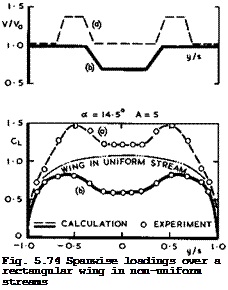
and distributed vorticity. In this form, it was put to the test by H Schlichting & W Jacobs (1940) and found to represent the spanwise loadings surprisingly well, considering the many simplifications made in its derivation,

 |
as can be seen from the examples in Fig. 5.74.
Large interference forces may arise when a jet passes close to a wing. These may be beneficial and may be exploited, as in the case of an external jet flap, where a jet underneath a wing may be diverted over a deflected trailing – edge flap and increase lift. Such an inviscid incompressible flow has been treated theoretically by C A Shollenberger (1973) for a simplified twodimensional model in which the aerofoil and the jet are represented by distributions of singularities. This approach has proved to be promising, but further theoretical and experimental work is needed before a design method is established which can deal with the numerous parameters which are typical of such lift-augmentation systems.
The main shortcoming of the existing theories is that the flow models themselves that are amenable to theoretical treatment are too idealised. In practice, the flows are always highly threedimensional and the non-uniformity may be caused by a turbulent jet of near-circular cross-section, the position of which relative to the wing is not always known precisely. We must, therefore, rely mainly on experiments to obtain the design information required.
In such experiments, not only must the full-scale conditions of the wing flow be simulated correctly but also the conditions in the jet or wake. Such experiments are, therefore, very difficult to perform. This emphasises once again the need for adequate experimental tools.
As an overall rule (see D Kiichemann & J Weber (1953)), we may assume from the existing results that the total lift increment, directed towards the region with higher velocity, can be put into the form
acl – TT ■ fi“tf2r f3E * <5-“>
JpVqDc
where D is a suitable lateral dimension of the jet or wake. This is to
signify that the circulation around a lifting wing will be changed in proportion to its angle of incidence; that the displacement flow around a thick wing will acquire a circulation (as in Fig. 5.72); and that viscous entrainment at an inflow angle є will also contribute a force increment. Our knowledge about the latter effect is particularly poor but its magnitude appears to be relatively small, at least for jets. Some rough empirical values for the factors fj and f2 have been obtained by H Falk (1944), from low-speed tests on a rectangular wing with a nearby jet. These factors depend on the geometrical position of the wing relative to the jet, on the (exit) velocity ratio between the jet and the mainstream, and also on the ratio between the thickness of the wing and the (exit) diameter of the jet. The factor f2 has its maximum near the edge of the jet and is an antisymmetrical function of the distance between wing and jet, as indicated in Fig. 5.73. In the definition of (5.44), the factor f] has a maximum when the wing is near the centre line of the jet, simply because the local value of is highest there in
the field. These tests indicated that all these effects of non-uniformities in the stream are indeed significant and cannot be ignored. Most of the interference effects are detrimental and unfavourable and, in view of the many uncertainties in determining their magnitude, it seems safest to design aircraft so that these effects do not matter. For example, it will be safest, on present knowledge, to put the tailplane in a position where it is never likely to be affected by the wake behind the wing or by the jet from the engines.
The tests by Falk were made mainly near that initial part of the jet where a core with full exit velocity still existed, and thus gave relatively orderly results. What happens further downstream where a wing may be subjected to a highly-turbulent stream poses quite different problems and has not yet been clarified.
This leads us to the general problem of the behaviour and response of aircraft when flying through air which is itself in non-uniform motion, where the direction and magnitude of the velocity vary both in space and time. Largely because of our ignorance, we call this condition atmospheric turbulence (for a beautiful pictorial presentation of our atmosphere see R Scorer (1972)). The problems involved are so difficult to solve that it has been said (J A Dutton (1970)), "man, like the birds, baffled gravity, but the winds still baffle him: the wind is still free, its song hardly heard, and until he takes the measure of that music, man’s flight is fettered". The severity and the importance of these problems have been recognised from the beginning, ever since the first successful powered aircraft was damaged beyond immediate repair by a sharp gust of wind at Kitty Hawk (see 0 Wright (1913)). Since then, a vast number of papers on the subject have appeared, and we refer here to the review articles by H A Panofsky & H Press (1962), J Burnham (1970), G Coupry (1970) and J A Dutton (1970), as well as to the papers published in AGARD Conference Proceedings Nos.48 and 140 on the aerodynamics of atmospheric shear flows and on flight in turbulence. The atmospheric turbulence may even affect the speed of aircraft (see e. g. J В W Edwards (1973)) and also the way an aircraft should be piloted (see e. g. G Coupry (1974)). Surface winds, in particular, affect the design and operation of aircraft (see e. g. AGARD R-626 (1974)).
The problem begins with fundamental difficulties in describing the state of the atmosphere: examination of records of atmospheric turbulence taken under a wide variety of conditions shows two conflicting trends: one towards order and the other towards disorder and chaos. Consider the latter first. In this case, turbulence appears to have a predominantly irregular or random pattern and may be modelled mathematically in the simplest way as a stochastic process
with a Gaussian structure of the velocity field. The distinctive feature of the Gaussian process is that all its statistical properties are specified by a single function, the power spectrum (for a discussion of these concepts in the present context, see e. g. H A Panofsky & H Press (1962); and P G Saffman
(1968) ). On the hypothesis that the only forces acting on the air are inertial forces which transfer energy from large scales to smaller scales of motion, dimensional analysis then leads to the conclusion that there should exist a region in which the power spectrum is proportional to the 5/3-power of the frequency or the wave number of the disturbances (see C F von WeizsUcker
(1948) ). Some flight measurements do confirm this effect (see e. g. J Burnham & J T Lee (1969), A McPherson & J M Nicholls (1969), J A Dutton (1970)), on the average. Thus atmospheric turbulence may contain energies at frequencies from hundreds of Hertz down to fractions of one Hertz. In various parts of this frequency range, different phenomena may occur, which are of interest to the aircraft engineer (see e. g. J К Zbrozek (1961), J К Zbrozek & J G Jones
(1967) , A McPherson (1973)).
At very low frequencies, below 10“^Hz, say, disturbances may pose a navigation problem. This, we may assume, the pilot should be able to deal with. Between about 10“2 and 10Hz, stability and control problems appear, e. g. as a result of normal accelerations. At the lower end (somewhat below 10“2hz for large aircraft and somewhat above this for small aircraft), the aircraft may be put into a phugoid motion (see section 5.10 below). But the contribution of the phugoid frequency to the acceleration response of the aircraft is usually negligibly small and, again, the pilot should be able to stabilise the aircraft, provided the magnitude of the disturbances is not so great as to lead to excursions beyond the safe flight envelope, such as stalling. At the higher end (between 10-1 and 1Hz for large aircraft and around 1Hz for small aircraft), short-period oscillations may be excited, in which the whole aircraft oscillates as a result of the restoring aerodynamic forces following a disturbance. These lie in a range where the pilot’s influence begins to wane, and the short-period frequency may be close to the limiting frequency which the pilot can control. He may often be able to alter the response of the aircraft but he may not be able to reduce the peaks of normal acceleration consistently. In addition to these aerodynamic effects, structural problems of aeroelasticity and of loads and fatigue appear. To give only one example, a fuselage bending mode may appear at some characteristic frequency (between 1 and 10Hz for large aircraft). Most of these effects cannot be influenced by aerodynamic design, other than by providing effective flight controls, and other means are being sought to improve matters. One is to provide airborne means for the detection of turbulence some distance ahead of the aircraft so that such regions can be avoided. Another is the use of electronic devices to alleviate the effects of gusts and so to provide a smoother ride (see e. g.
E J Bulban (1973)).
There are some well-developed theories for calculating the unsteady forces on wings in a ‘disorderly’ turbulent flow, if the assumptions can be made that the gust velocities are small as compared with the average flight speed; that the equations of motion can be linearised; and that any form of prescribed gust field as well as its effects can be built up by Fourier superpositions.
The responding aircraft is then assumed to be always in a state of equilibrium with a continuous random input of disturbances. A general method for unsteady flows of this kind was developed by Th von Karman & W R Sears (1938) and applied by W R Sears (1941) to calculate the lift on an aerofoil passing through a onedimensional sinusoidal upwash wave pattern. H W Liepmann (1952) and (1955) used statistical concepts of power-spectral-density techniques (PSD) and autocorrelation analysis to calculate the lift on threedimensional wings in a random gust field. In this approach, the gust field is assumed to have a fixed spatial distribution which is convected past the aerofoil. In an alternative approach by H S Ribner (1956), the field is regarded as a superposition of plane sinusoidal wave motions of all orientations and wavelengths. This has been used by J M R Graham (1970) and (1971) to obtain general results for wings of infinite span and also of finite span and rectangular planform. This theory has been checked and found satisfactory in experiments by R Jackson et al (1973), which were carefully designed to reduce the scatter often found in other experiments of this kind.
These PSD techniques have dominated gust research for some time and have been made mandatory by some certification authorities. But they are deficient in that they are not suited to describe important events when isolated, discrete gusts occur and stand out in a clearly identifiable manner, which have large effects on aircraft response. To deal with these in a more appropriate way,
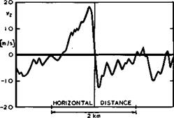
J G Jones (1968), (1969) and (1973) has proposed an alternative discrete-gust model and developed this into a straightforward engineering method for the evaluation of aircraft response. In this approach, the non-Gaussian nature of many events and forcing functions in a turbulent atmosphere is taken into account, recognising that some of the motions which are commonly regarded as turbulent may contain some degree of inherent order rather than a Gaussian chaos (see e. g. R S Scorer (1969), Susan M Damms & D KUchemann (1972)). An example of such an orderly structure is shown in Fig. 5.75 from results of
|
Fig. 5.75 Vertical gust velocity measured in patch of turbulence near storm tops. After Burns (1972) |
flight tests near storm tops by Anne Burns (1972). The similarity between the flow implied in these results and the flow near a vortex core, to be discussed in section 6.3, is striking. The scale of the region of concentrated vorticity in the atmosphere is impressive.
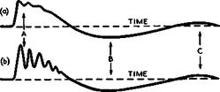
In Jones’s theory, the concept of a discrete gust is employed as an elementary building-brick. Such a gust may be thought of as having the form of a ‘ramp’ and the main parameters describing it are then the gust intensity, i. e. the change in one of the velocity components, and the gradient distance, i. e. the length over which the velocity change is spread out. As an example to indicate how an aircraft may respond to such a transient ramp gust, the normal acceleration which the gust-induced loads cause in the longitudinal motion of the aircraft, that includes heaving, pitching, and wing-bending, is shown in
|
Fig. 5.76. In general, the structural loads on the aircraft depend on a
|
Fig. 5.76 Transient response of aircraft to ramp gust. After J G Jones (1973)
combination of moderately well-damped rigid-body modes and relatively lightly – damped structural aeroelastio modes. In case (a) in Fig. 5.76, the response is dominated by the rigid-body motion; the ‘fine structure’ at the primary ‘macroscale’ response peak (at A) and the typical subsequent overswings (at В and C) are illustrated. In case (b), a structural component of significant amplitude is included. To determine peak responses and limit-loads for a prescribed gust pattern is, of course, a much more complicated problem which has not yet been completely solved. It has been suggested (J G Jones (1973)) that the discrete-gust treatment is appropriate in cases like (a) in Fig. 5.76, with safety factors incorporated to allow for effects of flexibility. A PSD analysis appears to be preferable in situations where the response is completely dominated by a lightly-damped structural mode. To deal with cases where rigid-body and flexible modes make roughly equal contributions to critical peak responses requires further work.
Of the many other important aspects of flight in turbulence, we mention here only the safety problems of an aircraft which is subjected to large gust disturbances during a landing approach or take-off and refer to the work of J G Jones (1971) on turbulence models for the assessment of handling qualities during take-off and landing and of J G Jones (1973) on the application of energy management concepts to flight-path control in turbulence. In this research, piloted ground-based simulators can be a useful tool (see e. g.
J G Jones & В N Tomlinson (1971)).


