Stability Characteristics from Eigenvalue Analysis
The lifting-surface flutter of immediate concern can be described by a linear set of structural dynamic equations that include a linear representation of the unsteady airloads in terms of the elastic deformations. The surface could correspond to a
wing or stabilizer either with or without control surfaces. Analytical simulation of the surface is sometimes made more difficult by the presence of external stores, engine nacelles, landing gear, or internal fuel tanks. Although such complexities complicate the analysis, they do not alter significantly the physical character of the flutter instability. For this reason, the following discussion is limited to a “clean” lifting surface.
When idealized for linear analysis, the nature of flutter is such that the flow over the lifting surface creates not only steady components of lift and pitching moment but also dynamic forces in response to small perturbations of the lifting-surface motion. The wing airfoil at a local cross section undergoes pitch and plunge motions from lifting-surface torsional and bending deformation, respectively. When a lifting surface that is statically stable below its flutter speed is disturbed, the oscillatory motions caused by those disturbances die out in time with exponentially decreasing amplitudes. That is, we could say that the air provides damping for all such motions. Above the flutter speed, however, rather than damping out the motions due to small perturbations in the configuration, the air can be said to provide negative damping. Thus, these oscillatory motions grow with exponentially increasing amplitudes. This qualitative description of flutter can be observed in a general discussion of stability characteristics based on complex eigenvalues.
Before attempting to conduct an analysis of flutter, it is instructive to first examine the possible solutions to a structural-dynamic representation in the presence of airloads. We presume that a flight vehicle can be represented in terms of its normal modes of vibration. We illustrate this with the lifting surface modeled as a plate rather than a beam. This is more realistic for low-aspect-ratio wings but, in the present framework, this increased realism presents little increase in complexity because of the modal representation. For displacements w(x, y, t) in the z direction normal to the plane of the planform (i. e., the x-y plane), the normal mode shapes can be represented by фі (x, y) and the associated natural frequencies by. A typical displacement of the structure can be written as
n
w(x, y, t) = &(t)фі y) (5.!)
І =1
where &i (t) is the generalized coordinate of the іth mode. For simplicity, both rigid – body and elastic modes are included in this set without special notation to distinguish them from one another. The set of generalized equations of motion for the flight vehicle can be written as
Mi(&i + mf&i) = Si (i = 1, 2,…,n) (5.2)
where Mi is the generalized mass associated with the mass distribution m(x, y) and can be determined as
The generalized force S (t), associated with the external loading F(x, y, t), can be evaluated as
Si (t) = // F(x, y, t)фі (x, y)dxdy (5.4)
planform
Recall that of the set of natural frequencies ші, any that are associated with rigid-body modes are equal to zero.
To examine the stability properties of the flight vehicle, the only external loading to be considered is from the aerodynamic forces, which can be represented as a linear function of w(x, y, t) and its partial derivatives, plus a set of additional states that may be needed to represent pertinent aspects of the flow field, such as the induced flow or downwash. It is presumed that all other external disturbances have been eliminated. Such external disturbances normally would include atmospheric gusts, store-ejection reactions, and so forth. Recalling that the displacement can be represented as a summation of the modal contributions, the induced-pressure distribution, Ap(x, y, t), can be described as a linear function of the generalized coordinates, their derivatives, and the flow-field states. Such a relationship can be written as
n N
Ap(x, y, t) = [aj ^, y)ij(t) + bj(x, y)lj(t) + Cj(x, y)lj(t^ + J2 dj ^, У)х j(t)
j=1 j=i
(5.5)
where the Xs are state variables associated with the flow field, sometimes called “augmented” states or “lag” states, written here so as to have the same units as the generalized coordinates. The number of these states is denoted by N > 0, which may be distinct from n. The corresponding generalized force of the і th mode now can be determined from
 |
||
Following the convention in some published work, we factored out the freestream air density px and U2/b2 from the aerodynamic generalized force expression. Although not necessary, this step enables analysts to identify altitude effects more readily. It also shows explicitly that all aerodynamic effects vanish in a vacuum where px vanishes. Moreover, the normalization involving powers of b/U—where b is a reference semi-chord of the lifting surface—allows the matrices [a], [b], [c], and [d] to have the same units, simplifying the equations in terms of dimensionless variables that follow later. Any inhomogeneous terms in the generalized forces can be eliminated by redefinition of the generalized coordinates so that they are measured with respect to a different reference configuration. Thus, the generalized equations of motion can be written as a homogeneous set of differential equations when this form of the generalized force is included. They are
Matrices [A] and [ E] can be obtained from unsteady-aerodynamic theories as well as from computational fluid dynamics or test data. Note that matrix [ E] may be an operator that differentiates {f} one or more times.
This system consists of n + N equations—that is, the number of structural modes (including both elastic and rigid-body modes) plus the number of aerodynamic states, respectively. The general solution to this set of linear ordinary differential equations can be described as a simple exponential function of time because they are homogeneous. The form of this solution is taken as
fi (t) = f i exp(vt) hi (t) = hi exp(vt) (5.10)
Substituting this expression into Eqs. (5.7) and (5.8), we obtain a set of algebraic equations, each term of which contains exp(vt). After factoring out this term, the result is n + N simultaneous linear, homogeneous, algebraic equations for the f s, which may be written in matrix form as
![]() {f} – Px [p2[c] + p[b] + [a]] {f} – px[d]{X} = {0}
{f} – Px [p2[c] + p[b] + [a]] {f} – px[d]{X} = {0}
![]() [P[A] + [I]] Д} – [E] {f} = {0}
[P[A] + [I]] Д} – [E] {f} = {0}
where p = bv/U is the unknown dimensionless eigenvalue, and the symbol [M] denotes a diagonal matrix with elements Mi. For a nontrivial solution of the generalized coordinate amplitudes, the determinant of the array formed by the coefficients of f i and Xi must be zero. It is apparent that this determinant is a polynomial of degree 2n + N in p. The subsequent solution of this polynomial equation for p yields 2n + N roots consisting of nc complex conjugate pairs and nr real numbers where 2nc + nr = 2n + N. A typical complex root has the form
vk = —p = Г* ± i Uk k = 1, 2,…,nc (5.12)
whereas the roots vk with к = nc + 1, nc + 2,…,nc + nr are real. In other words, any root can be written as vk so that, ^k = 0 for nc < к < nc + nr.
—(k)
For each root pk, there are corresponding complex column matrices f j, j = 1, 2,…,n, and Xj, j = 1, 2,…, N. Thus, the solution for the displacement field from the generalized equations of motion with the aerodynamic coupling can be written as
Hc +nr
w(x, y, t) = ^ {wk(x, y) exp [(Tk + i&k)tj + Wk(x, y) exp [(Tk – i&k)tj} (5.13)
k=1
where wk is the complex conjugate of wk. This expression for w(x, y, t) turns out to be real, as expected. Each wk represents a unique linear combination of the mode shapes of the structure; viz.
n
Wk(x, y) = ^2 ?(k)^i (x, y) (k = 1, 2,…,nc + nr) (5.14)
i =1
—(k)
Note that only the relative values of f i can be determined unless the initial displacement and rate of displacement are specified.
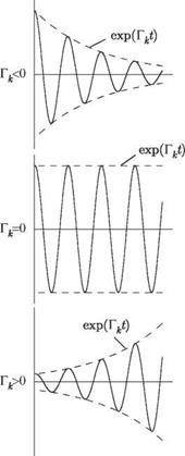
It is apparent from the general solution for w(x, y, t), Eq. (5.13), that the kth component of the summation represents a simple harmonic oscillation that is modified by an exponential function. The nature of this dynamic response to any specified initial condition is strongly dependent on the sign of each Tk. Typical response behavior is illustrated in Fig. 5.1 for positive, zero, and negative values of Tk when ^k is nonzero. We note that the negative of Tk is sometimes called the “modal damping” of the kth mode, and ^k is called the “modal frequency.” It is also possible to classify these motions from the standpoint of stability. The convergent oscillations when Tk < 0 are termed “dynamically stable” and the divergent oscillations for Tk > 0 are “dynamically unstable.” The case of Tk = 0 represents the boundary between the two and is often called the “stability boundary.” If these solutions are for an aeroelastic system, the dynamically unstable condition is called “flutter” and the stability boundary corresponding to simple harmonic motion is called the “flutter boundary.”
Recall from Eq. (5.13) that the total displacement is a sum of all modal contributions. It is therefore necessary to consider all possible combinations of Tk and ^k, where Tk can be < 0, = 0, or > 0 and ^k can be = 0 or = 0. The corresponding
 |
type of motion and stability characteristics are indicated in Table 5.1 for various combinations of Гк and Qk. Although the primary concern here is in regard to the dynamic instability referred to as flutter, for which ^k = 0, Table 5.1 shows that the generalized equations of motion also can provide solutions to the static-aeroelastic problem of divergence. This phenomenon is indicated by the unstable condition for ^k = 0, and the divergence boundary occurs when Гк = ^k = 0.
In many published works on flutter analysis, the method outlined in this section based on determination of stability from complex eigenvalues is known as the
|
Table 5.1. Types of motion and stability characteristics for various values of Гк and Qk
|
|
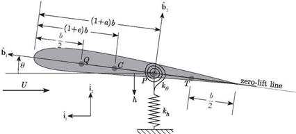
Figure 5.2. Schematic showing geometry of the wing section with pitch and plunge spring restraints |
“p method.” It is named for the dimensionless complex eigenvalue p = bv/U that appears in Eq. (5.11); p is frequently termed a “reduced eigenvalue.” To provide an accurate prediction of flutter characteristics, the p method must use an aerodynamic theory that accurately represents the loads induced by transient motion of the lifting surface. Depending on the theory, augmented aerodynamic states may or may not be necessary; for example, the theory outlined in Section 5.5.2 uses them, whereas the theory in the next section does not; rather it uses the simplest steady-flow theory for which no claim of accuracy is made. The sole purpose of doing so is to illustrate the use of the p method to analyze a simple configuration.


