SWEPT WING MODIFICATIONS FOR STALL
From the previous discussion of the characteristics of simple swept wings operating at high angles of attack, it is apparent that changes are needed to prevent tip stall and the positive pitching moment prior to and after the development of. The modification should not lead to an increase in drag near stall nor should decrease the lift drag ratio of the design condition or spoil the other desirable qualities of the wing.
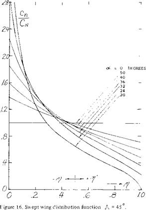 Modifications to improve stall and pitching moment are needed for swept wings operating at the take off and landing condition and at high speeds. At take off and landing the effects of flaps, slats and other leading edge devices must be considered. During high speed operation the drag of such devices is high so only clean wings with low drag characterises are used.
TWIST AND CAMBER MODIFICATION. In the case of straight tapered wings it was shown in Chapter IV that the undesirable tip stalling could be eliminated by changing the load distribution on the wing. This change was made with tapered wings by reducing the angle of attack at the tip, “wash out”. A similar change could have been made to make the wing stall inboard by increasing the section camber or the wing chord on the outboard stations, in the case of straight wings a relatively simple change in load distribution will correct the tip stalling problem.
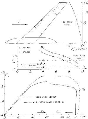
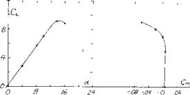
With swept wings, especially those with high aspect ratio and sweep angle, such corrections in load distribution do not necessarily eliminate tip stalling and the corresponding positive pitching moment. For instance in the case of a 45° swept aspect ratio 6 wing with а Л = .5, an increase of camber to CL^ = .8 and 10 degrees of wash out did not eliminate tip stalling (10,a). As shown on figure 17, this highly modified wing still has the undesirable positive pitching moment at stall.
The large increase in CLX on the inboard stations due to the boundary layer flow makes it extremely difficult to correct tip stalling with the application of twist and camber. As noted on figure Clx is 50% above the value based on section data at the.545 wing station. At the tip stations however, the CLX is nearly equal to the value expected from section data. To make the wing stall inboard first, large changes in the spanwise distribution
|
Figure 17. Camber and washout changes to improve usable operating lift coefficient (l, a). |
|
|
|
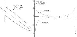
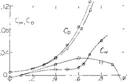
Figure 18. Lift and pitching moment characteristics of a 35° swept wing designed for constant Ck = .8 without auxiliary devices (10,e). |
angle or camber are required and the changes necessary will increase with aspect ratio and sweep angle. The large increase in camber and angle outboard will be undesirable from drag consideration, thus it may be desirable to increase the taper and so reduce the tip chord to obtain the desired loading.
A design study and experimental program (10,e) to investigate the performance of a wing with a constant spanwise pressure near C^x was conducted to determine if the local stall could be made to occur inboard. The wing investigated had a sweep angle,-A. = 35°, A = 7.04 and t/c = 10%. The twist and camber distribution used to obtain a constant CL near maximum lift is shown on figure 18. It should be noted that the wing has an extensive twist and camber change from root to tip, including the use of negative camber inboard.
The tests did indicate that the operating CL was constant across the span near the stall angle taking into account Reynolds number and local flow problems at the wing root. The test data, figure 18, however, indicated that as the wing stalls a strong pitch up moment is encountered. Although the pitch up moment would be expected for a similar simple swept wing, the modification of camber, chord and twist should have been sufficient to give the desired negative pitching moment. The boundary layer flow and detailed vortex distribution of the swept wing must change the detailed section pressure distribution to develop the positive pitching moment. Since large variations of twist, camber and chord appear to only partially improve the characteristics of a swept wing, other devices must be employed to achieve the desired results.
BOUNDARY LAYER FENCES. In the earliest days of propeller-driven airplanes the engine nacelles usually in mid-wing position (and in the slipstreams) may have prevented any spanwise boundary layer transport. In singleengine airplanes and in all modern configurations where the jet engines are mounted, whether below the wing or behind the wing at the sides of the fuselage, the boundary layer transport described previously can be reduced by fences (thin plates) placed on the upper wing surface. The fences may be used across the entire wing chord or may cover only the leading or trailing edges. The use of wing fences is to effectively dam the boundary layer air and to direct it back on the wing in the direction of flow so that the effect of the inboard section is not felt by the outboard section.
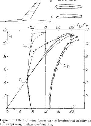
The use of fences for control of the boundary layer on wings has been investigated for many different combinations of sweep and aspect ratio. For instance, on a wing with 40° sweep and A = 7 (11,a) full chord streamwise fences were tested along with various other configurations. In general the usable operating CL was increased before an unstable moment was encountered, but even with the largest number of fences the pitch up moment was not eliminated, figure 19. The fences tended to increase the wing L/D at the higher lift coefficients but as might be expected reduced the L/D at low CL. A reduction in size and number appeared to reduce the usable operating CL (ll, c). The lack of success of fences for eliminating the adverse pitching moment can be attributed to their localized action. For instance, consider the variation of spanwise loading and section maximum lift coefficient as illustrated in figure 15. The section CLX decreases toward the tip because of the spanwise flow of boundary layer. With the addition of a fence, as shown, tho action of the spanwise flow is decreased locally with the result that locally the value of ClY is equal to the two dimensional value. However the boundary layer action again develops outboard of the fence in this case, it has little effect on the overall value of CLX for the wing. For this reason, except in a few specialized cases, the use of fences will have limited success.
(11) Effect of Wing Fences on Swept Wings:
a) Dickson, Swept Airplanes With Fences, NACA RM A55C30a.
b) Sutton, Sweptback Wing with Four-Digit Sections to M = 0.92, NACA RM A54L08.
c) Bray, Fences on Longitudinal Stability, NACA RM A53F23.
d) Sutton, Fuselage-Tail Combinations – A – = 40, 45, 50, NACA RM A57F06a.
e) Hieser, Swept Wing with Nacelles, NACA TN 1709
|
|
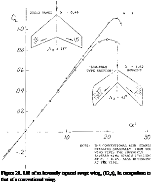
INVERSE TAPER. A radical attempt at preventing wing – tip stalling is shown in figure 20. The chord increasing toward the wing tips is expected to prevent stalling simply by reducing the lift coefficient near the tips. In comparison to a conventional (tapered) wing comparable in aspect ratio and angle of sweep, it is seen that the lift curve slope is reduced. Assuming that the influence of the increased- length lateral edges may be cancelled by their rounded shape, we may conclude that the influence of lift distribution (loaded near the wing tips) is responsible for an increased average induced lift angle. As a matter of fact, when extrapolating the functions in figure 9 of Chapter III into the field of taper ratios above unity, we obtain for Л = 1.6, a correction ДА in the order of —0.5. Notwithstanding the considerable differences in aspect ratio and the angle of sweep, a similar value is found when evaluating the experimental slope in figure 20 within the range of small lift coefficients. As to stalling, that begins at CL = 0.4 or 0.5 (as reported in (12,a) on the wing tips. This type of flow separation is also evident in the drag which increases rapidly to a level some 100% above that of the conventional swept wing, figure 8, Chapter XV. Note also, that the maximum lift coefficient (although for a different unidentified foil section) is appreciably reduced. In conclusion, increasing the chord outboard does not really help improve the characteristics of swept back wings.
(12) Taper Effects:
a) Purser, Various Sv/ept Shapes, NACA TN 2445.
b) Polhamus, Airplane Configuration Effects on Static Stability, NACA RM L56A09a.
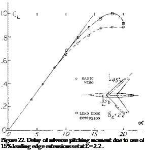
 A typical example of leading edge wing extension is shown on figure 22 for. A. = 45° and A = 6. As noted on figure 9, the wing would be expected to have a strong pitch up moment at high operating lift coefficients. By adding a 15% leading edge extension at the.55 semi span station, the pitch up moment was delayed to a CL = .95 as compared to.6 for the basic wing. The use of larger extensions spanwise appeared to improve the pitching moment characteristic; however, if too much of the wing is covered by a leading edge extension, (15,a) the inboard sections of the wing again become too effective with the result that the tip will stall first. The correct length of the leading edge extension must be selected for each combination of sweep angle and aspect ratio.
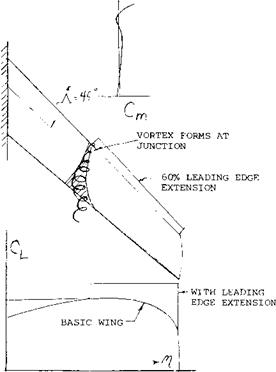
In addition to improving the flow around the airfoil the leading edge extension will develop a vortex at its inboard end. This vortex, as shown in figure 23, is shed and flows chordwise effectively blocking the spanwise flow of the air in the boundary layer. This allows the outboard section to develop a higher C in relation to the inboard sections and improves the effectiveness of the leading edge extension. Tests (13) have been made of slots in the wing to duplicate this vortex with limited success in improving the CL where the pitching moment breaks in the stable direction.
(13) 
 Leading Edge Extensions Swept Wings:
a) Kelley, H. N., Low Speed Tests -A = 45°, A := 5, NACA RML55H19.
b) Good son and Few, Extension & Fence Tests, A = 45 , A = 4, NACA RML52K21.
c) Whitcomb & Norton, Extension, Notches & Droop A = 45°, NASA TN D834.
d) Sutton, Extensions for A = 40 , A = 7, NACA RM 55129.
e) Liner, Martz, Three Extensions, 55, 65 7 70%, A = 450 ? a = 5, NACA RM L53B02.
0 Lowry & Schneiter, Slots and Extensions & A Variations, A = 60°, NACA TN 1284.
g) Demele, Inverse Taper Leading Edge Flap, – A = 45 , NASA TN D138.
h) Weil & Morrison, Notches, Extension and Fences and Fences, Л = 45° , A = 4, NACA RM L5 3J27Ja.
i) Goodson, Leading Edge Chord Extensions, A = 4,-Л – = 40°, NACA RM L52118.
j) Spreeman, Chord Extensions, Flaps & Fences, M = .4 to.9, A = 4, A = 45° , NACA TN 3845.
k) West, Chord Extension, Fences, M = .4 to 1.03, A = 4,-Л – = 45°, NACA RM L53B02.
l) Furlong, A Summary Low Speed Longitudinal Characteristics – Swept Wing, NACA TR 1339.
m) TN 3040.
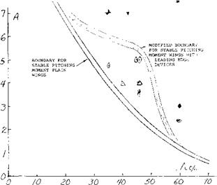
As a result of the use of slats and leading edge extensions the critical angle of sweep is improved as a function of aspect ratio, as illustrated on figure 24. Thus based on the available test data stable pitching moments can be obtained at higher angles of sweep or aspect ratios with the proper choice of leading edge devices. Two dimensional airfoil characteristics and the methods described previously can be used to find the size of the extensions needed. In general, the size becomes critical with increasing sweep angles.
|
Сы
Figure 23. Formation of vortex at leading edge extension junction blocking boundary layer (9,a). |
(14) Compressibility Effects on Maximum Lift:
a) Hall, Swept Wing Flow Pattern, M = .6 to 1.6, ARC R&M 3271.
b) Mayers, Transonic Buffet 60 Swept Wing AIAA Paper 69-793.
c) Sutton, Buffet Investigation of an Airplane Configuration, NACARM A57F06a.
d) Ray, Buffet Characteristics Swept Wings, NASA TN D5805.
e) Turner, Lift, Drag and Pitching for Swept Wing in Transonic Range, NACA Transonic Conference 1949.
f) Whitcomb, Bodies added on a wing for high speed. NACA TN 4293
|
Figure 24. Critical angle of sweep as modified by leading edge devices. |


