The jet flap
It was shown in Chapter 6 that the highest CLmax obtainable with an ordinary flap is about 2.7. This chapter treats the jet flap, where power is expended to generate much higher CLmax’s. The pure jet flap utilizes a jet of air only at the trailing edge, deflected downward, whereas the blown flap consists of a physical flap that directs a sheet of air blown over its upper surface. The two flaps are similar in their behavior in that a sheet of high – momentum air is directed downward from the trailing edge of the airfoil. In turning in the direction of the mainstream, this sheet of air can sustain a pressure difference across it which deflects the main stream. The pressure difference between the upper and lower surfaces of the airfoil does not have to vanish at the trailing edge. The result is an increased lift on the airfoil and a rearward shift in the center of pressure.
The jet flap was investigated as early as 1933 by Shubauer [1], but it was not until the development of the turbojet, with its ready supply of blowing air, that the application became feasible. It has even been proposed that the lifting system be completely combined with the propulsion system, for theoretically all of the jet momentum is recovered as thrust as the jet ultimately aligns itself in the free-stream direction.
Lift Performance
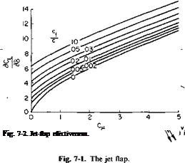
A jet flap is shown in Fig. 7-1. A jet with a mass flow rate of m – s and a velocity of Vj leaves the trailing edge of a deflected flap at an angle of S relative to the zero lift line of the airfoil section. This line, in turn, is at an angle of attack of a. As shown later, and as might be suspected, the lift coefficient of the airfoil can be divided into two parts:
 (7-1)
(7-1)
As might also be suspected, the derivative SCJ85 is a function of the ratio of Cf to c. It is also, however, a function of the momentum in the jet expressed in a dimensionless form as a momentum coefficient:
![]() = 4th
= 4th
qc
 |
C„ is a “lift coefficient” of sorts, for m-Vj would be the jet force or reaction. Indeed, one way of determining Сц experimentally is simply to measure the
reaction statically. However, some error is introduced because of the entrainment of the surrounding air. Instead, is usually determined from the measured mass flow rate and, assuming an isentropic expansion of the jet, from measured reservoir conditions in or just before the jet.
The derivative dCJda. is a function only of and is equal to dCJdd for
cy/c equal to one. Figure 7-2 presents dCJdd as a function of Сц for various values of the ratio of cf to e. For cy/c of 0 the values are given by
A
~ = [4тгС„(1 + 0.151СУ2 + 0.139СД)]1/2, (7-3)
For intermediate values of cfjc, Fig. 7-2 can be used, or we can interpolate between Eqs. (7-3) and (7-4) by using the results for Сд = 0 developed in Chapter 6.
Equations (7-3) and (7-4) are interpolations of theoretical results obtained by Spence [2] and are covered in more detail later. Reference 3 derives similar derivatives for a wing of finite aspect ratio. For the wing of aspect ratio A (7-3) and (7-4) are multiplied by a factor
where
(1 – QCJnA ° C – (1 – QCJnA
к _________ 2Cl / (a + S)
^ nA + 2(дС1/да) – 2tc(1 + a)
This implicit relation for F(A, CM) is unwieldy. Instead, for the usual case, it is sufficiently accurate to use an approximation for F(A, Cfl) which holds for small CM or large A.
FM r A + 2C"/7r n fit
1 ’ ^ “ A + 2 + 0.604C*’2 + 0.876СИ ( ’
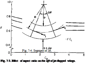
Equation (7-6) is presented graphically in Fig. 7-3.
Before continuing, the theory of the thin jet-flapped airfoil from which Eqs. (7-3) and (7-4) were obtained must be examined. The general procedure presented in Ref. 2 by Spence is followed, but for the sake of simplicity some of the mathematical exactness and manipulations have been forsaken.
Consider a segment of the jet aft of the airfoil shown in Fig. 7-4. The mass rate of flow through the jet is т} and the velocity is ty. If we assume a pressure difference of Ap across the jet, then, from the momentum theorem
applied to the differential element, we can write
ntjVj A6 = ApR Л0 or
![]() A mJVJ
A mJVJ
where R is the radius of curvature of the jet.
The reaction of the jet on the flow external to the jet is
F = ApR Д0.
A vortex of strength per unit length along the jet of у would produce a reaction of
F = pVyR A0.
 |
Hence, equating these two forces, we can calculate the action of the jet on
the flow external to the jet by replacing the jet with a running vortex strength yj given by
The total lift on the airfoil is equal to the sum of the lift due to the circulation around the airfoil and the vertical component of the jet reaction.
L = pVTc + trijVj sin (a + 5). (7-9)
It is of interest to consider further the contribution of the jet in light of (7-8). For a nearly horizontal jet with a large radius of curvature (7-8) becomes
where x is distance downstream of the airfoil and у is the vertical location of the jet sheet positive downward. This can be integrated from x = 0 to x = oo to obtain the total circulation around the jet Г}.
|
~mjvj f* PV Jo |
Tj = у dx
dy/dx is zero at infinity and for small angles is equal to a + 3 at x = 0. Hence Tj becomes
Г,. = ^(а + <5). (7-11)
Hence from (7-11) the total lift becomes
L = pV(Tc + Г j). (7-12)
If (7-12) is divided by %pV2c, the airfoil lift coefficient is obtained as
![]() тл’
тл’
Because the jet is ultimately turned in the direction of the free stream, the thrust produced is theoretically equal to the flux of jet momentum:
T = mfj
![]() C – T T %pV2c
C – T T %pV2c
= CL
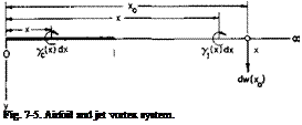 |
We are now in a position to formulate the boundary value problem which must be solved to determine Гс and Г,. Referring to Fig. 7-5, the
airfoil, which lies on the x-axis between 0 and 1, is replaced by a running vortex strength of yc(x) given by
7c(x) = Vf(x). (7-15)
The jet sheet lies between x = 1 and сю and is represented by the vortex distribution given by (7-10). In a manner similar to that for thin airfoil theory both у-distributions are assumed to lie along the x-axis, and the boundary conditions are also satisfied along the x-axis.
Now consider the velocity induced downward at a location x0 by the two vortex distributions. This can be calculated as
![]() , . Г ycdx f00 Jjdx Ч*0) = ———- + —1
, . Г ycdx f00 Jjdx Ч*0) = ———- + —1
 |
|
Jo 27c(x0 – x) J1>0 2л:(х0 –
![]()
For a flat plate airfoil at an angle of attack of a ^ = a for 0 < Xn < 1
|
2na., 0 < x0 < 1, (7-19) 2я/(:х0), *o > 1. (7-20) |
 |
Hence (7-16) becomes a pair of simultaneous integro-differential equations
subject to the boundary conditions
/(1) = a + S,
/(со) = 0.
From here on the reduction and solution of Eqs. (7-19) and (7-20) become an exercise best left to the mathematician. The ultimate solution is not expressible in closed form. However, those students who are mathematically inclined are urged to refer to the original reference by Spence for a very challenging analysis.
The numerical results of Spence’s solution have already been presented in the form of Eqs. (7-3) and (7-4), which are simply interpolated fits to the results that hold closely for C„ values up to 10. These theoretical calculations agree remarkably well with experimental results, even for flap deflections as high as 60°, where we would expect serious departures from linearized theory.
The slope of the lift curve for ordinary airfoils is less than that predicted from thin airfoil theory and is attributable to the growth of the boundary layer which relaxes the Kutta condition at the trailing edge. In the jet – flapped airfoil the jet definitely fixes the trailing edge condition. In fact, the slope of the lift curve is higher for the jet-flapped airfoil than thin-wing theory predicts. This discrepancy is attributable to the effects of finite thickness. An allowance for thickness can be made by assuming that it affects the lift resulting from circulation around the airfoil as it does in the case of C,, = 0. For an ordinary airfoil of thickness ratio t/c the lift is higher than that predicted by thin airfoil theory by a factor of approximately (1 + t/c). Thus Eq. (7-13), corrected for thickness, becomes
c‘ = Vc f1 + 0 + c"(a + 5)
Equation (7-1), corrected for thickness ratio and aspect ratio, therefore becomes
where dCJda. and dC,/d5 are obtained from Fig. 7-2 or Eqs. (7-3) and (7-4) and F, from Fig. 7-3 or Eq. (7-6).
Reference 4 offers two additional corrections to (7-21) to account for part-span flaps and fuselage cut-out; X and v are presented as corrections to the lift increment resulting from jet deflection 8 and wing incidence a, respectively. These corrections are obtained from such relatively simple considerations as
Я = | (7-22)
_ S'(dCJda) + (5 – S"KdCl/da)’Cu=0 V S{dCJd a) ’ 1 " ’
where S is the gross wing area and S’ is the reference wing area corresponding to the spanwise extent of the jet slot. CL, based on S, then becomes
The derivatives in (7-24) are understood to be for two-dimensional, or infinite aspect ratio, thin wings. CM is also based on S.
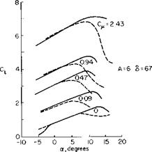
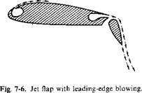
So far we have been concerned only with the increments to CL and not with the maximum value of CL that can be obtained with a jet-flap. There are two effects that must be considered as limiting CL. First is the real-fluid effect of the flow separating from the upper surface of the airfoil and second is the limiting effect on CL for finite aspect ratio wings due to the deflection of the trailing vortex sheet discussed in Chapter 3. It is somewhat risky to generalize on CLmax for jet flaps in view of the many complications involved. At low Сц values the jet-flapped airfoil tends to be limited by leading-edge separation. This causes a slight decrease in the incidence angle of one or two degrees at which Ctmax is obtained, as compared with the Cw = 0 case. As Сц is increased above approximately 2, however, the boundary layer control afforded by the jet apparently prevents leading-edge separation and results in increases in a for Cimax as great as 6 to 8° at Сц of the order of 7. Leading-edge separation can be reduced by the use of drooped leading edges or highly cambered thick sections. Leading-edge blowing is also another means of preventing leading-edge separation, as shown in Fig. 7-6.
The effect of Cp and nose droop on the CL versus a curve, shown in Fig. 7-7, is taken from Ref. 4. At each См the effect of the droop is to increase the incidence angle for stall about 5°. From this figure the difference “max — “max (C„ = 0) is plotted versus Сд and presented in Fig. 7-8. Also plotted on the figure are some points taken from Ref. 5. In the absence of actual test data it is recommended that this curve, together with the methods of Chapter 6, be used to estimate Cimax for a jet-flapped wing. For extremely
![]()
|
|
|

high values of predicted C, max, however, that part due to circulation after the jet reaction has been subtracted should be checked against the limiting CL as a function of aspect ratio derived in Chapter 3.
Pitching Moment
The nose-down pitching moment of a jet flap is high for two reasons. First, the center of pressure of the circulatory lift moves aft with increasing Cfl and second the vertical component of the jet reaction acts at the trailing
|
Fig. 7-9. Theoretical change of Cm with C,. |
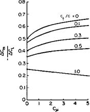
edge. Theoretical values of the change in pitching moment with lift coefficient change due to flap deflection only, as obtained by Spence [4], are presented in Fig. 7-9. Values of cfjc from 0 to 1.0 are covered. In general, for a flat-plate airfoil Cm would be written as
|
|
where (dCJdC,)3=conslani is obtained from Fig. 7-9 and the (<5C,/d<5)0=conslant is obtained from Fig. 7-2. The corresponding derivatives with respect to a, with S a constant, are obtained from the same figures with cf/c = 1.0.
Experimental results are not included on Fig. 7-9, but in general they agree reasonably well with the theoretical predictions.
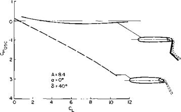
A possible method of counteracting the high nose-down pitching moments associated with jet flaps is given in [5]. In Fig. 7-10 a double-hinged flap is used to redirect the jet reaction to a point forward of the trailing edge. In the present case it was directed through the midchord point. A significant improvement in Cm as a function of CL resulted.
|
Fig. 7-Ю. Effect of double-hinged flap on midchord pitching moment. |
Downwash
A problem to be overcome with the application of jet flaps is the large amount of downwash produced at the horizontal tail. It appears useless even to consider theoretical estimates of the downwash, for experiments have shown them to be in considerable error. Instead, some experimental measurements taken from Refs. 4 and 5 are presented in Fig. 7-11 which should be of some help in estimating the downwash angle e. It becomes readily apparent that all-movable tails will have to be used with jet-flapped aircraft, for downwash angles of the order of 30° may be encountered.


