TRANSIENT RESPONSE TO AILERON AND RUDDER
We have seen previously that useful lateral steady states are produced only by certain definite combinations of the control deflections. It is evident then that our interest in the response to a single lateral control should be focussed primarily on the initial behavior. The equations of motion provide some insight on this question directly. Following a step input of one of the two controls the state variables at t = 0+ are all still zero, and from (5.13,20) we can deduce that their initial rates of change are (using the compact notation)
Щ =
Dp = £Єф (10.6,1)
Dr = Жф
The initial sideslip rate Djj is not of much interest, but the rotational accelerations are. From the last two equations
Dm = (i &ъ + кЖд)д
and for t —*■ 0, m = (ij£^ + кЖй)ід (10.6,2)
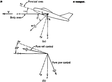
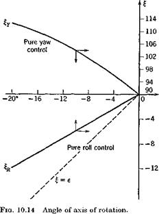
Thus the resultant angular velocity vector, and hence the initial instantaneous axis of rotation, lie in the plane of symmetry as illustrated in Fig. 10.13. Let us investigate the angle {that to makes with the x axis for the two cases of “pure” controls, i. e. when only one of Clg or Gns is not zero. For the roll – control case, 6′ = 0 and
nO
From the definitions given in (5.13,20), (10.6,3) becomes
and is zero if Izx = 0, i. e. if Cx is a principal axis. This is just as expected,
of course, that a moment applied about a principal axis produces rotation about that axis. When Izx is not zero, we get from (5.4,206)
![]()
![]()
![]()
 |
(I, — I„ ) sin e cos є
Z j, Xp’
|
|
vehicle. For vehicles that are slender, such as the SST or a slender missile, the trend indicated above is very much accentuated. In the limit Ix —»• 0, both
(10.6,4) and (10.6,5) give the limit
tan £ = tan e
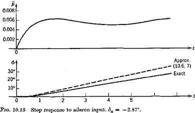
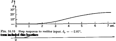
which indicates that the vehicle will initially rotate about its principal x axis no matter what the direction of the applied-moment vector. If this rotation were to persist through 90°, then /? would be equal to |e| and a would be reduced to zero. The above analysis tells us how the motion starts, but not how it continues. For that we need solutions of the complete system equations (5.13,20). Solutions for the example jet transport at CLe = .25 at 30,000 ft altitude were obtained by analog simulation of these equations, and the results for fi, р, ф, and ip are shown on Figs. 10.15 and 10.16. Figure 10.15 shows the response to negative aileron angle (corresponding to entry into a right turn). The main feature is the rapid acquisition of roll rate, and its integration to produce bank angle ф. The maximum roll rate is achieved in about 1| sec, and a bank angle of about 25° at the end of 6 sec. Because of the aileron adverse yaw derivative, Cng > 0, the initial yawing moment is negative, causing the nose to swing to the left, with consequent negative ip and positive p. The positive />, via the dihedral effect G^ < 0 produces a
negative increment in Gv opposing the rolling motion. More than 4 sec elapse before the nose swings into the desired right turn.
Figure 10.16 shows the response to a negative (right) rudder angle of the same magnitude as the aileron angle on Fig. 10.15. This causes the nose to swing rapidly to the right, /5 being initially roughly equal and opposite to tp indicating virtually no change in the direction of the velocity vector. The result of ft < 0 (because of C'(/j/3) is a positive rolling moment and positive ф.
Right rudder, like right aileron, is seen to produce a transition into a turn to the right, but neither does so optimally. A correct transition into a truly banked turn requires the coordinated use of both controls, and if there is to be no loss of altitude (see Sec. 10.4) of the elevator as well.
An approximation to the ф response to <5a can be obtained from the single – degree-of-freedom roll analysis corresponding to (9.7,7). With the aileron
0
6" – 4° –
 |
2» –
Df = &£ + &» da
![]()
 |
or АБ2ф – А^рВф = £ЄьЬа
The solution of (10.6,6) for zero initial conditions is
This result is compared with the exact solution on Pig. 10.15 and is seen to give a good approximation to ф over the most important first few seconds. This simple analysis supplies a useful criterion for roll control. It yields as
the steady-state roll rate,
A requirement on pss for a given vehicle then leads to an aileron design to provide the necessary Glf da.


