Transonic Flow around a Finite Wing
 |
 |
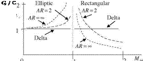
Aerodynamically and practically useful three dimensional transonic analyses over finite wings date back to 1940s with implementation of swept wing concept (Polhamus 1984). According to the information given by Polhamus, the first prototype flown with swept wing was Me262 for which the drag rise because of the compressibility of the air was delayed with 40° sweep at the leading edge which enabled the plane to increase its speed. This fact had not been realized by the allied forces yet. Busemann’s theory on supersonic swept wings was implemented for reducing the effect of compressibility on subsonic wings in wind tunnel testings at 1941. In 1945, however, Jones was the first, except German aerodynamicists, to start testing swept wings for their aerodynamic utilizations (Jones 1946). A decade after Busemann, Jones’ experimental and analytical work independently gave the lift coefficient variations for various wings with respect to the free stream speed, Fig. 6.10. According to Fig. 6.10, the lift coefficient for thin delta wings remains the same except for M? = 1. This means, the Jones’ theory on thin delta wings
state that the compressibility effect at low angles of attack is insignificant at even very high speeds as high as free stream Mach number of 2. That is if we somehow know the lift coefficient of a thin delta wing for incompressible flow, we can safely use that value even for very high speeds. The effect of the aspect ratio of a wing is also shown in Fig. 6.10 for elliptic and rectangular wing forms.
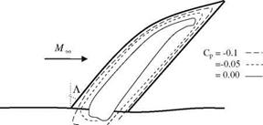
The theory of Jones and the information confiscated from Germans helped the designing of the military and the civilian transonic and supersonic aircrafts having swept wings. In this respect, until 1960s the studies were in general under military contracts; therefore, they were classified. In following years, first the experimental results were presented and/or published in relevant literature (Lock 1962). In his experimental work, Lock designed a 12% thick wing with 55° sweep and a curved leading edge, as shown in Fig. 6.11, at 2.5° angle of attack to give a shockless lifting wing at 0.90, 1.00 and 1.1 free stream Mach numbers. The design lift coefficient of the wing is CL = 0.18. Also shown in Fig. 6.11 are the pressure coefficient contours for the non lifting wing at free stream Mach number of 1. A similar work was performed on a similar wing shape experimentally and numerically by Labrujere and his associates at free stream Mach number M? = 0.96 and surface pressure distribution similar to that given in Fig. 6.11 is (Labrujere et al. 1968).
The evolving of the shape of the wing from Fig. 6.11 to its later stages with swept but straight leading edges and with smaller aspect ratios is the given in detail by Kucheman in later years (Kucheman 1978). In later years, with the advent of more sophisticated numerical methods the transonic wing design with higher lift coefficients with small aspect ratios became possible.
 |
 |
So far we have seen the application of the three dimensional potential theory to obtain the surface pressure distribution and the lift coefficient of the wings in transonic flow. The lift coefficient obtained with the potential theory is usually small, i. e. CL = 0.18, since the potential theory is valid for wings at small angles of attack without the presence of shocks and flow separation. In order to obtain higher lift coefficients, we have to increase the angle of attack to the level of partial flow separation, which in turn forces us to perform the viscous flow analysis via numerical solution of some form of Navier-Stokes equations. As an example, we can give the detailed numerical study over a specially designed swept wing, Wing C, performed by Kaynak implementing a zonal solution technique based on
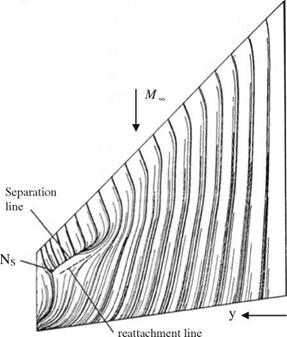
the Euler and Navier-Stokes solutions in mid 1980s (Kaynak 1985). Shown in Fig. 6.12 is Wing C planform and its skin friction lines obtained numerically with the following geometric and flow parameters. The leading edge of the wing has 45° sweep, aspect ratio of 2.6 and spanwise twist of 8.17°. The free stream Mach number is 0.85, the angle of attack is 5.9° and the Reynolds number is 6.8 x 10⁶. In zonal approach, the viscous region around the wing surface is solved with the thin shear layer equation and the outer region is solved with Euler equations (Kaynak 1985). The skin friction lines on the wing surface in Fig. 6.12 indicate that the flow is attached on most of the wing surface, however, only on the tip region there is a local separation due to presence of a shock, and the flow reattaches afterwards in 50-70% spanwise location.
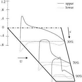
In Fig. 6.13, the surface pressure plots are provided at different spanwise locations. From these curves, the presence of a shock at the tip region is visible from 70% spanwise towards the tip itself.
 |
 |
In a transonic regime under the off-design conditions, the increase in the total drag and the decrease in the total lift of a wing show similar drastic changes as shown by a profile in 2-D flow. In this respect a transonic wing has to be redesigned in order to operate in off-design conditions. For this purpose, redesigning process based on the numerical solution of the Navier-Stokes equations is applied on a transonic wing successfully by Jameson. In his work, a transonic
 |
|
wing at buffeting Mach number of 0.86, is re-designed for performance increase under off-design conditions (Jameson 1999).


