UNSTEADY LIFTING-SURFACE SOLUTION BY VORTEX RING ELEMENTS
The method of transforming steady-state flow-based numerical solutions into the time-dependent mode is described schematically in Fig. 13.25 and in the introduction to Section 13.10. In this section the same approach is applied to the three-dimensional thin lifting-surface problem. In this example, as in the case of the lifting surface of Section 12.3, the wing’s bound circulation and the
|
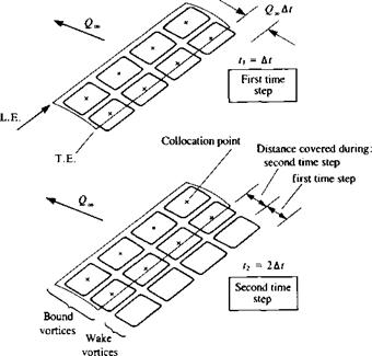
FIGURE 13.30 Vortex ring model for the unsteady lifting surface during the first time step (upper) and during the second time steps (lower figure). |
vortex wake will be modeled by vortex ring elements (see Fig. 13.30). The main advantage of this element is in the simple programming effort that it requires (although its computational efficiency can be further improved). Also, in this numerical example, the boundary conditions are specified on the actual wing surface, which can have camber and various planform shapes.
The solution is again based on the time-stepping technique, and at the beginning of the motion only the wing bound vortex rings exist (upper part of Fig. 13.30). Note that the closing segment of the trailing edge vortex elements in Fig. 13.30 will represent the starting vortex. Consequently, during the first time step there will be no wake panels and if the wing is represented by К unknown vortex rings (K = 8 in Fig. 13.30), then by specifying the zero normal flow boundary condition on the К collocation points a solution at t = At is possible. During the second time step, the wing is moved along its flight path and each trailing edge vortex panel sheds a wake panel with a vortex strength equal to its circulation in the previous time step (lower part of Fig. 13.30). With this model, therefore, we do not have to add an additional equation to enforce the Kelvin condition since the vortex ring formulation inherently fulfills this condition. During this second time step, there will be only one row of wake vortices, but with a known strength. Therefore, the wing К bound vortices can be calculated for this time step, too, by specifying the boundary condition on the same К collocation points. This time-stepping methodology can then be continued for any type of flight path and at each time step the vortex wake corner points can be moved by the local velocity, so that wake rollup can be simulated. One of the advantages of this wake model is in its simplicity, and its being equal in its formulation to the wing’s bound vortex rings (or constant-strength doublet panels); consequently, this wake model can be used for more advanced panel methods (and is actually used by the code PMARC9 6,9 7,12 13).
It is recommended that prior to reading this section the reader should be familiar with the steady-state solution presented in Section 12.3. The presentation of the unsteady version of this method then proceeds with the same sequence (steps) of the previous sections. So, in general, the wing is divided into panel elements containing vortex ring singularities as shown in Fig. 13.30 and the solution procedure is as follows:
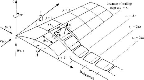
Choice of singularity element. The method by which the thin-wing planform is divided into panels is similar to what is described in Section 12.3 and shown schematically in Figs. 13.30 and 13.31. The leading segment of the vortex ring is placed on the panel’s quarter-chord line and the collocation point is at the center of the three-quarter chord line. The normal vector n is defined at this point, too, which falls at the center of the vortex ring. A positive Г is defined here according to the right-hand rotation rule, as shown in the figure.
|
FIGURE 13.31 Nomenclature for the unsteady motion of a thin lifting surface along a predetermined path. (Note that in this figure, too, the fluid is at rest and the airfoil moves toward the left side of the page.) |
j
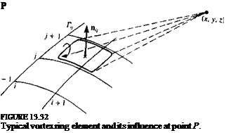 From the numerical point of view these vortex ring elements are stored in rectangular patches (arrays) with i, j, indexing as shown by Fig. 13.31 (see also Fig. 12.10). The velocity induced at an arbitrary point P (де, у, z), by a typical vortex ring (see Fig. 13.32) at location ij can be computed by applying the vortex line routine VORTXL (Eq. (10.116)) to the ring’s four segments:
 |
(и,, vu w,) = VORTXL(x, y, z, xu, уіф zQ, xiJ+l, yiJ+l, z, v+1, Г,.,)
The velocity induced by the four vortex segments is then
(u, v, w) = (uit vu w^) + (u2, v2, w2) + (m3, v3, w3) + (m4, v4, w4) (13.133)
It is convenient to include these computations in a subroutine (see Eqs.
(10.117) and (12.17)) such that
![]() (и, v, tv) = VORING(x, y, z, i, j, Г)
(и, v, tv) = VORING(x, y, z, i, j, Г)
Note that in this formulation it is assumed that by specifying the i, j counters the (jc, y, z) coordinates of this panel are automatically identified (see Fig. 12.10).
The use of this subroutine can considerably shorten the programming effort; however, for the inner vortex rings the velocity induced by the vortex segment is computed twice. For the sake of simplicity this routine will be used for this problem, but more advanced programming can easily correct this loss of computational effort.
It is recommended at this point, too, to calculate the velocity induced by the trailing vortex segments only (the vortex lines parallel to the free stream,
as in Fig. 12.5). This information is needed for the induced drag computations and if done at this point will only slightly increase the computational effort. The influence of the trailing segments is obtained by simply omitting the (ut, Vi, Wj) + (и3) v3, и’з) part from Eq. (13.133):
(u, v, w)* = (u2, v2, w2) + (u4, ^4, w„) (13.135)
and it is assumed that (и, v, w)* is automatically obtained as a byproduct of subroutine VORING.
Kinematics. Let us establish an inertial frame of reference X, Y, Z, as shown in Fig. 13.1, such that this frame of reference is stationary while the wing is moving to the left of the page. The flight path of the origin and the orientation of the x, y, z system is assumed to be known and is prescribed as:
X0 = X0(t) Yn=Y0(t) Zu = Z0(t) (13.136)
ф = ф(і) в = 6(t) ф = p(t) (13.136a)
and the momentary velocity of the origin and the frame’s rotations about the axes are
*о = ЛГо(0 Z0 = Z0(t) (13.137)
Ф = Ф( t) e = d(t) Ф = Ф(1) (13.137a)
For example, if the wing moves to the left (parallel to the X axis) at a constant speed of f/„ and has a constant sideslip (parallel to the Y axis) of 14, then
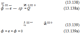 and
and
It is useful to establish a transformation between the two coordinate systems (Eq. (13.7a)) that depends on the translation of the origin and the orientation of the body frame of reference:
/X-Хо
![]() =/(0, в, V)(
=/(0, в, V)(
Z-Z0
This transformation, without the translation part, can be used also for the velocity transformation. To define such a three-dimensional transformation uniquely, the order of rotation must be specified. For example, if we adopt the order of rotation such that first we rotate about the z axis, then about the у
axis, and finally about the x axis then the transformation becomes:
 |
Rotation by ip (sideslip)
 |
Rotation by в (angle of attack)
 |
|
Rotation by ф (roil angle)
where U3, КЗ, W3 are the velocity component, observed in the x, y, z frame due to the translation of the origin.
The time-dependent kinematic velocity components U(l), K(f), W(t), in the x, y, z frame are then a combination of the translation velocity and the rotation of the body frame of reference:
 (13.141)
Since the instantaneous rotation and translation rates are known, these kinematic terms are known, too, at each time step.
Discretization and grid generation. The method by which the thin wing planform is divided into elements is the same as presented in Section 12.3 and is shown in Figs. 13.30 and 13.31. Some typical panel elements are also shown in Figs. 12.8-12.10. Also, if only the wing’s semispan is modeled then the mirror image method must be used to account for the other semispan. The leading segment of the vortex ring is placed on the panel’s quarter-chord line and the collocation point is at the center of the three-quarter chord line (see Fig. 13.31). The lifting surface is usually given by z = r)(x, y) and is divided into N span wise and M chord wise panels. Using a procedure such as shown in Fig. 12.13 allows the scanning and calculation of geometrical information such as the panel area Sljt normal vector n,; and the coordinates of the collocation points. A simple and fairly general method for evaluating the normal vector is shown in Fig. 12.11. The panel opposite corner points define two vectors A
and B, and their vector product will point in the direction of n
A XB П-|АХВ|
A positive Г for a vortex ring is defined here using the right-hand rotation convention, as shown in Fig. 13.31. Also, for increased surface curvature the above-described vortex rings will not be placed exactly on the lifting surface, and a finer grid needs to be used, or the wing surface can be redefined accordingly. By placing the leading segment of the vortex ring at the quarter-chord line of the panel the two-dimensional Kutta condition is satisfied along the chord (recall the lumped-vortex element).
At this point also the wake shedding procedure must be addressed. Consider a typical trailing-edge vortex ring placed on the last panel row (as shown in Fig. 13.33). The trailing segment (parallel to the trailing edge) is placed in the interval covered by the trailing edge during the latest time step (of length Q ■ At). Usually it must be placed closer to the trailing edge within
0. 2-0.3 of the above distance (see discussion about this topic at the beginning of Section 13.8.2). The wake vortex ring corner points must be created at each time step, such that at the first time step only the two aft points of the vortex ring are created. Therefore, during the first time step there are no free wake elements and the trailing vortex segment of the trailing edge vortex ring represents the starting vortex. During the second time step the wing trailing edge has advanced and a wake vortex ring can be created using the new aft points of the trailing edge vortex ring and the two points where these points were during the previous time step (see Fig. 13.30). This shedding procedure is repeated at each time step and a set of new trailing-edge wake vortex rings are created (wake shedding procedure).
The strength of the most recently shed wake vortex ring (Г^( in Fig. 13.33) is set equal to the strength of the shedding vortex ГТЕ.(_Л( (placed at the trailing edge) in the previous time step (as if it was shed from the trailing edge
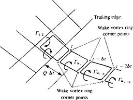 FIGURE 13.33
Nomenclature for the wake shedding procedure at a typical trailing edge panel.
and left to flow with the local velocity):
ІЧ = Гт. е.,„лі (13.142)
Once the wake vortex is shed, its strength is unchanged (recall the Helmholtz theorems in Section 2.9), and the wake vortex carries no aerodynamic loads (and therefore moves with the local velocity).
This is the unsteady equivalent of the Kutta condition. For the steady-state flow conditions, all wake panels shed from a particular trailing edge panel will have the same vortex strength, which is equal to the strength of the shedding panel. Thus, the spanwise-oriented vortex lines of the adjacent vortex rings will cancel each other and only a horseshoe-like vortex will remain.
Influence coefficients. At this point, the zero normal flow across the solid – surface boundary condition is implemented. In order to specify this condition, the kinematic conditions must be known and the time-stepping loop (shown in Fig. 13.25) is initiated. Let us select again I, as the time-step counter, so that the momentary time is
t = /, • Af
Let us assume that at t = 0 the two coordinate systems x, y, z and X, Y, Z coincided and the wing was at rest. The calculation is initiated at t = At and the wake at this moment consists of the vortex line created by the trailing segments of the trailing edge vortex rings (Fig. 13.30). The location of the trailing edge at t = 0 and at t = Af, which is needed for specifying the wake panels’ corner points, is obtained by using coordinate transformations such as Eq. (13.140).
The normal velocity component at each point on the camberline is a combination of the self-induced velocity, the kinematic velocity, and the wake-induced velocity. The self-induced part can be represented by a combination of influence coefficients, as in the steady-state flow case. If the shape of the wing rj(x, у ) remains constant with time then these coefficients will be evaluated only once. The normal velocity component due to the motion of the wing is known from the kinematic equations (Eqs. (13.13a), or (13.141)) and will be transferred to the right-hand side (RHS*) of the equation. The strength of the other wake vortices is known from the previous time steps and the wake-induced normal velocity on each panel will be transferred to the right-hand side too.
Let us establish a collocation point scanning procedure (similar to that of Section 12.3) that takes the first chordwise row where і = 1 and scans spanwise with j = l—*N and so on (recall that we have M chordwise panels—see Fig. 12.10). This procedure can be described by two “DO loops” shown in Fig.
12.13. As the panel scanning begins, a sequential counter assigns a value К to each panel (the sequence of К is shown in Fig. 12.14) which will have values from 1 —* M x N.
Once the collocation point scanning has started, К — 1 (which is point
(і = 1, j = 1) on Fig. 12.12. The velocity induced by the first vortex ring is then
(u, v, wOu = VORING(jc, y, z, i = , j = ,Tl = 1.0)
Note that a unit strength vortex is used for evaluating the influence coefficient
 «и = («, v, tv),! • nj (13.143)
To scan all the vortex rings influencing this point, an inner scanning loop is needed with the counter L – 1 —>N X M (see Fig. 12.13). Thus, at this point, the К counter is at point 1, and the L counter will scan all the vortex rings on the wing surface, and all the influence coefficients aXL are computed (also, in Eq. (13.143) the ( )ц index means К = 1, L = 1):
aiL = (u, v, w)1L – Пі
and for the K, Lth panel
aKL = («, v, w)KL • nK (13.143a)
As mentioned before, parallel to the computation of the aKL coefficients, the normal velocity component induced by the streamwise segments of the wing vortex rings can also be computed. These bKL coefficients, which will be used for the induced drag calculation, are calculated by using Eq. (13.135)
bKL = (u, v, w)*KL • nK (13.144)
and it is assumed that these coefficients are a byproduct of the aKL calculations and do not require additional computational effort.
This procedure continues until all the collocation points have been scanned and a Fortran example for this influence coefficient calculation is presented in Fig. 12.13 of Chapter 12.
Establish RHS vector. Specifying the zero normal velocity boundary condition on the surface (Q„K = 0) at an arbitrary collocation point К results in
QnK = «апГ| + ак2Г2 + акзГ3 + • • • + aKmTm
+ [f/(f) + Uw> Y(0 + vw> lY(t) + • и* = 0
where [U(t), V(t), W(r)k are the time-dependent kinematic velocity components due to the motion of the wing (Eq. (13.141)), (uw, vw, ww)K are the velocity components induced by the wake vortices, and m = M x N. The wake influence can be calculated using Eq. (13.134) since the location of all vortex points is known (including the wake vortex points). Since these terms are known at each time step, they can be transferred to the right-hand side of the equation. Consequently, the right-hand side (RFIS) is defined as
RHS* = -[l/(f) + uw, V{t) + vw, W(t) + wwK • nK (13.145)
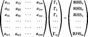
Solve linear set of equations. Once the computations of the influence coefficients and the right-hand side vector are completed, the zero normal flow
boundary condition on all the wing’s collocation points will result in the following set of algebraic equations:
|
|
(Recall that К is the vertical and L is the horizontal matrix counter and the order of this matrix is m = M X N.)
The results of this matrix equation can be summarized in indicial form (for each collocation point К) as
m
2>KLrL = RHS* (13.146)
L= 1
If the shape of the wing remains unchanged then the matrix inversion occurs only once. For time steps larger than 1 the calculation is reduced to
Г* = 2 e«.RHSt (13.147)
L=1
where a^L. are the coefficients of the inverted matrix.
Computation of velocity components, pressures and loads. For the pressure distribution calculations the local circulation is needed, which for the leading – edge panel is equal to Гц but for all the elements behind it is equal to the difference Г^ — Г,_іг The fluid dynamic loads then can be computed by using the Bernoulli equation (Eq. (13.24)) and the pressure difference is given by Eq. (13.123):
Ар = A – P. – p[(f)_ – (f)(+ (^)_ – (™) J
t, and t are the panel tangential vectors in the і and j directions (of course, these vectors are different for each panel and the ij subscript from t,-.. is dropped for the sake of simplicity).
The velocity-potential time derivative is obtained by using the definition ф*=± y/2 dl and by integrating from the leading edge. Since for this vortex
ring model ДФ = Г,
 (13.149)
Substituting these terms into the pressure difference equation results in Ару = pj[I/(f) + uw, V(t) + %, W(t) + wwtj • t, ‘ ^ –
Г _ j-*. ^ і
+ [U(t) + uw, V(t) + vw, W(t) + Hv],; • x, + J( r./j (13.150)
The contribution of this panel to the loads, resolved along the three body axes, is then
AF=-(ApAS)0n& (13.151)
The total forces and moments are then obtained by adding the contribution of the individual panels.
The total force obtained by this pressure difference integration will have some of the thin lifting-surface problems since it does not account for the leading-edge suction force. In general, the lifting properties of the wing will be estimated adequately by this method but the induced drag will be overestimated. Also, in the case of an arbitrary motion, the definition of lift and drag is more difficult and even the definition of a reference velocity (e. g., free-stream velocity) is not always simple. For example, presenting the pressure coefficient data on a helicopter blade in forward flight can be based on the local blade velocity or on the helicopter flight speed. So for the simplicity of this discussion on the induced drag, we shall limit the motion of the lifting surface such that it moves forward along a straight line without sideslip (but the forward speed may vary). The induced drag is then the force component parallel to the flight direction and each panel contribution is
A A, = p[(»,nd + wv),;,(r, y – Г,-еу) А Ьи + -| Г Ц А Бц sin or,,] (13.152)
and if the panel is at the leading edge then
![]() (13.152a)
(13.152a)
where ay; is the panel’s angle of attack relative to the free-stream direction. Also, the first term here is due to the downwash induced by the wing’s streamwise vortex lines ^ and due to the wake ww and the second term is
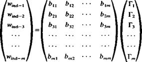
due to the fluid acceleration. The induced downwash wind at each collocation point i, j is computed by summing up the velocity induced by all the trailing segments of the wing bound vortices. This can be done during the phase of the influence coefficient computation (Eq. (13.144)) by using the VORING routine with the influence of the spanwise vortex segments turned off. This procedure can be summarized by the following matrix formulations where all the bKL and the are known:
|
|
where again m = N x M.
The main difficulty in the induced drag calculation for a general motion lies in the identification of the force component which will be designated as drag. Once this problem is resolved then the above method can be extended to more complex wing motions (and then angles such as <Хц in Eq. (13.152) must be defined).
Vortex wake rollup Since the vortex wake is force-free, each vortex must move with the local stream velocity (Eq. (13.21a)). The local velocity is a result of the velocity components induced by the wake and wing, and is usually measured in the inertial frame of reference X, Y, Z, at each vortex ring corner point. To achieve the vortex wake rollup, at each time step the induced velocity (и, v, w), is calculated and then the vortex elements are moved by
(Ax, Ay, Az)t = (u, v, w). At (13.153)
The velocity induced at each wake vortex point is a combination of the wing and wake influence and can be obtained by using the same influence routine (Eq. (13.134)):
m
(и, V, w)i = 2 VORING (xt, yh zt, i, j, TK)
K=l
Nw
+ 2 VORING (X/, У/, Zi, iw, jw, rW) (13.154)
*=i
and there are m wing panels and Nw wake panels.
In the case of a strong wake rollup the size of the wake vortex ring can increase (or be stretched) and if a vortex line segment length increases its strength must be reduced (from the angular momentum point of view). For the methods presented in this section it is assumed that this stretching is small and therefore is not accounted for.
Summary
The solution procedure is described schematically by the flowchart of Fig.
13.25. In principle, at each time step the motion kinematics is calculated (Eqs.
(13.141) ), the location of the latest wake vortex ring is established, and the RHS, vector is calculated. The influence coefficients appearing in Eq. (13.146) are calculated only during the first time step and the matrix is inverted. At later time steps, the wing vortex distribution can be calculated by the momentary RHS, vector, using Eq. (13.147). Once the vortex distribution is obtained the pressures and loads are calculated, using Eq. (13.151). At the end of each time step, the wake vortex ring corner point locations are updated due to the velocity induced by the flow field.
A student program based on this algorithm is given in Appendix D, Program No. 14.
|
Example 1. Sudden acceleration of an uncambered rectangular wing into a constant-speed forward flight. In this case the coordinate system is selected such
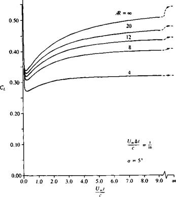
FIGURE 13.34 Transient lift coefficient variation with time for uncambered, rectangular wings that were suddenly set into a constant-speed forward flight. Calculation is based on 4 chordwise and 13 spanwise panels and t/„ At/с = |
that the * coordinate is parallel to the motion and the kinematic velocity components of Eq. (13.141) become [U(t), 0, 0]. The angle of attack effect is taken care of by pitching the wing in the body frame of reference and for the planar wing then all the normal vectors will be n = (sin a, 0, cos a). Consequently, the RHS vector of Eq. (13.145) becomes
RHS* = —{[£/(/) + uw sin a + ww cos a}K (13.155)
and here the wake influence will change with time. The rest of the time-stepping solution is as described previously in this section. For the numerical investigation the wing is divided into 4 chordwise and 13 spanwise equally spaced panels, and the time step is L4 At/c = 1/16.
Following the results of Ref. 13.12 the transient lift coefficient variation with time for rectangular wings with various aspect ratios is presented in Fig. 13.34. The duration of the first time step actually represents the time of the acceleration during which the ЭФ/dt term is large. Immediately after the wing has reached its steady-state speed (t/„) the lift drops due to the influence of the starting vortex and most of the lift is a result of the ЭФ/dt term (due to the
 |
{/,/
c
change in the downwash of the starting vortex—see Fig. 13.8, too). Also, the initial lift loss and the length of the transient seem to decrease with a reduction in the wing aspect ratio (due to the presence of the trailing vortex wake).
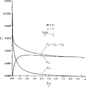
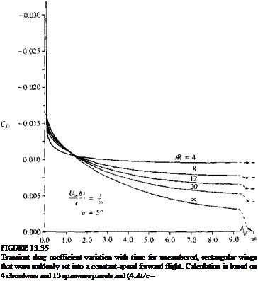
The transient drag coefficient variation with time for the same rectangular wings is presented in Fig. 13.35. Recall that this is the inviscid (induced) drag and it is zero for the two-dimensional wing (/R = ^-). Consequently, the larger aspect ratio wings will experience the largest increase in the drag due to the downwash of the starting vortices. The length of the transient is similar to the results of the previous figure, that is, a smaller aspect ratio wing will reach steady state in a shorter distance (in chord lengths).
The above drag calculation results allow us to investigate the components of Eq. (13.152). For example, Fig. 13.36 depicts the drag C0l due to induced downwash (first term in Eq. (13.152)) and due to the fluid acceleration term C„, (which is the second term in Eq. (13.152)) for a rectangular wing with an aspect ratio of 8. At the beginning of the motion, most of the drag is due to the ЭФ/dt term, but later the steady-state induced-drag portion develops to its full value.
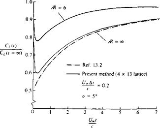
The effect of wing aspect ratio on the nondimensional transient lift of
|
FIGURE 13.36 Separation of the transient drag coefficient into a part due to induced downwash CD and due to fluid acceleration C„2. Calculation is based on 4 chordwise and 13 spanwise panels and Un ht/c = j(,. |
|
FIGURE 13.37 Effect of aspect ratio on the nondimensional transient lift of uncambered, rectangular wings that were suddenly set into a constant-speed forward flight. Calculation is based on 4 chordwise and 13 spanwise panels. |
uncambered, rectangular wings that were suddenly set into a constant-speed forward flight is shown in Fig. 13.37. This figure is very useful for validating a new calculation scheme, and is sensitive to the spacing of the latest wake vortex from the trailing edge (actually this is one method to establish the distance of the trailing edge vortex behind the trailing edge for a given time step). For comparison, the results of Wagner13 2 for the two-dimensional case are presented as well (in his case the acceleration time is zero and the lift at t = 0+ is infinite). It is clear from this figure, too, that the length of the transient and the loss of initial lift decreases with decreasing wing aspect ratio. The difference between the computed curve and the classical results of Wagner can be contributed to the finite acceleration rate during the first time step. The effect of this finite acceleration is to increase the lift sharply during the acceleration and to increase it moderately later (this effect of finite acceleration is discussed in Ref. 13.13).
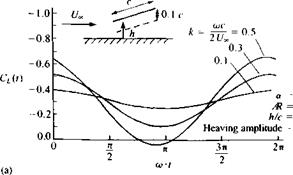
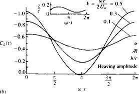
Example 2. Heaving oscillations of a rectangular wing. As a final example this method is used to simulate the heaving oscillations of a rectangular wing near the ground. The boundary conditions for this case were established exactly as in the example of Section 13.9.1. The ground effect is obtained by the mirror image method and the results1312 for an aspect ratio of 4, planar rectangular wing, are presented in Fig. 13.38. The upper portion shows the effect of frequency on the lift without the presence of the ground and the loads increase with increased frequency. The lower portion of the figure depicts the loads for the same motion, but with the ground effect. This case was generated to study the loads on the front wing of a race car due to the heaving oscillation of the body and the data
|
|
|
FIGURE 13.38 Effect of ground proximity on the periodic lift during the heaving oscillation of an aspect ratio = 4 rectangular wing. |
indicates that the ground effect does magnify the amplitude of the aerodynamic loads.


